Optical code division multiplexing communication method and system
- Summary
- Abstract
- Description
- Claims
- Application Information
AI Technical Summary
Benefits of technology
Problems solved by technology
Method used
Image
Examples
first embodiment
[0027]FIG. 3 is a block diagram showing the construction of an optical code division multiplexing communication system of the first embodiment (that is, a system capable of implementing an optical code division multiplexing communication method of the first embodiment) of the present invention. As shown in FIG. 3, the optical code division multiplexing communication system of the first embodiment includes a transmitter 41, a decoding device 43 connected to the transmitter 41 by a transmission line 42, and a receiver 44.
[0028] As shown in FIG. 3, the transmitter 41 includes a multi-wavelength optical pulse light source 41a for producing a wavelength multiplexing pulse, a data signal generator 41b, a wavelength multiplexing pulse modulator 41c which modulates a wavelength multiplexing pulse on the basis of a control signal from the data signal generator 41b, and an encoder which produces a multi-wavelength optical pulse train (for example, corresponding to optical pulses 31a, . . . ,...
second embodiment
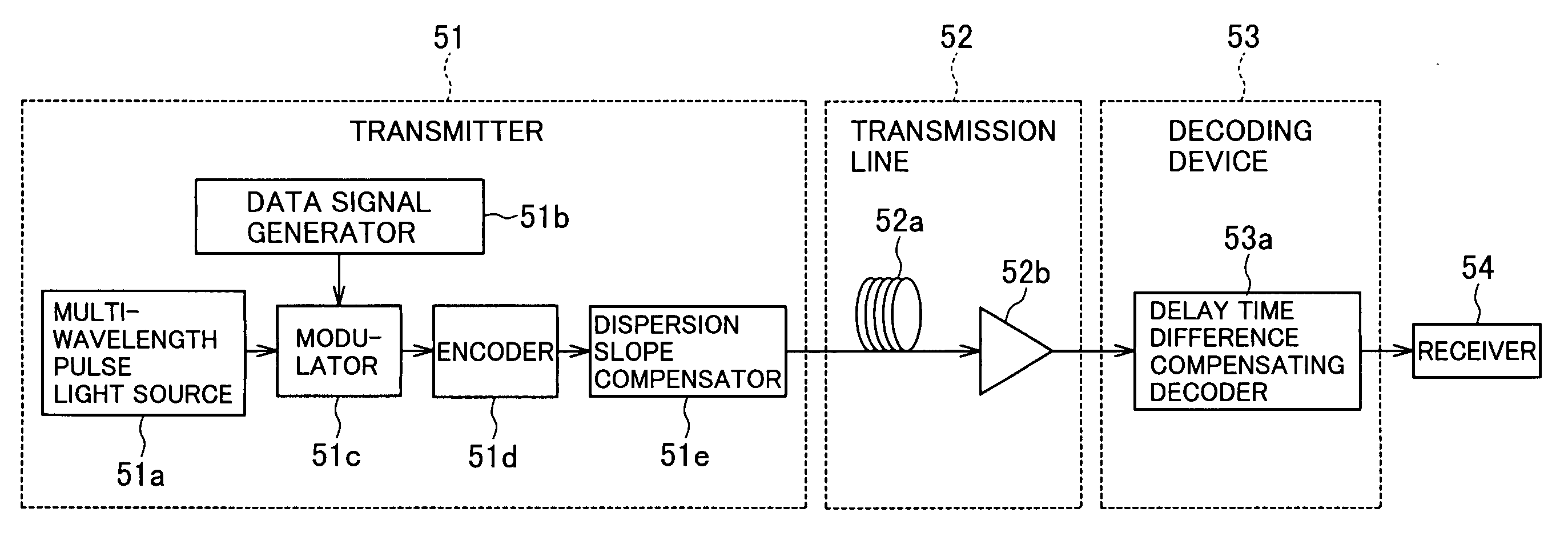
[0041]FIG. 8 is a block diagram showing the construction of an optical code division multiplexing communication system of the second embodiment (that is, a system capable of implementing an optical code division multiplexing communication method of the second embodiment) of the present invention. As shown in FIG. 8, the optical code division multiplexing communication system of the second embodiment is different, in that a dispersion slope compensator 51e is provided in the former stage of a transmission line 52, from the optical code division multiplexing communication system of the first embodiment in which the dispersion slope compensator (43b in FIG. 3) is provided in the latter stage of the transmission line (42 in FIG. 3).
[0042] A multi-wavelength pulse light source 51a, a data signal generator 51b, a modulator 51c, and an encoder 51d in FIG. 8 correspond to the multi-wavelength pulse light source 41a, the data signal generator 41b, the modulator 41c, and the encoder 41d in F...
third embodiment
[0046]FIG. 9 is a block diagram showing the construction of an optical code division multiplexing communication system of the third embodiment (that is, a system capable of implementing an optical code division multiplexing communication method of the third embodiment) of the present invention. As shown in FIG. 9, the optical code division multiplexing communication system of the third embodiment is different, in that a dispersion slope compensator 61e is provided in the former stage of a transmission line 62 and in that a dispersion slope compensator 63b is provided in the latter stage of the transmission line 62, from the optical code division multiplexing communication system of the first embodiment in which the dispersion slope compensator (43b in FIG. 3) is provided only in the latter stage of the transmission line (42 in FIG. 3).
[0047] A multi-wavelength pulse light source 61a, a data signal generator 61b, a modulator 61c, and an encoder 61d in FIG. 9 correspond to the multi-...
PUM
 Abstract
Description
Claims
Application Information
 - R&D
- Intellectual Property
- Life Sciences
- Materials
- Tech Scout
- Unparalleled Data Quality
- Higher Quality Content
- 60% Fewer Hallucinations
Browse by: Latest US Patents, China's latest patents, Technical Efficacy Thesaurus, Application Domain, Technology Topic, Popular Technical Reports.
© 2025 PatSnap. All rights reserved.Legal|Privacy policy|Modern Slavery Act Transparency Statement|Sitemap|About US| Contact US: help@patsnap.com


