Supercharge Your Innovation With Domain-Expert AI Agents!

Optical code division multiplexing communication method and system

a communication method and optical code technology, applied in the field of optical code division multiplexing communication method, can solve the problems of inability to produce auto-correlation waveform, inability to excellently decode encoded optical signals, and inability to produce fig. 1, and achieve excellent decoding and elongation of transmission distance

Inactive Publication Date: 2008-09-09
OKI ELECTRIC IND CO LTD
View PDF10 Cites 0 Cited by
  • Summary
  • Abstract
  • Description
  • Claims
  • Application Information

AI Technical Summary

Benefits of technology

The present invention provides an optical code division multiplexing communication method that can transmit an optical signal over long distances using a time-spreading / wavelength-hopping method. The method compensates for delay time differences between individual optical pulses and optical pulse spread in a time direction to improve the decoding of the wavelength multiplexing pulse. The invention also includes an optical code division multiplexing communication system and encoding and decoding devices that use this method. The technical effect of the invention is to further elongate the transmission distance of the optical signal.

Problems solved by technology

Hence, even if a decoder of the same codes as an encoder is used, the auto-correlation waveform as shown in FIG. 1 cannot be produced (that is, the encoded optical signal cannot be excellently decoded).
However, when the chromatic dispersion of an individual transmission line is compensated by known means such as a chromatic dispersion compensating fiber, the communication system needs to be increased in size, which results in increasing transmission loss and costs.
However, even if the decoder 21 shown in FIG. 2 is used, it is only a wavelength difference and a delay time difference caused by a transmission distance that are compensated, and the optical pulse spread in a time direction of individual optical pulse, which is caused by the chromatic dispersion of the fiber, cannot be compensated.
Hence, as the transmission distance is longer, the widths of auto-correlation waveforms are more expanded and the optical pulses finally overlap neighboring optical pulses, thereby making it impossible to receive the optical signal.
Therefore, the transmission distance cannot be more extended.

Method used


Image

  • Optical code division multiplexing communication method and system
  • Optical code division multiplexing communication method and system
  • Optical code division multiplexing communication method and system

Examples


first embodiment

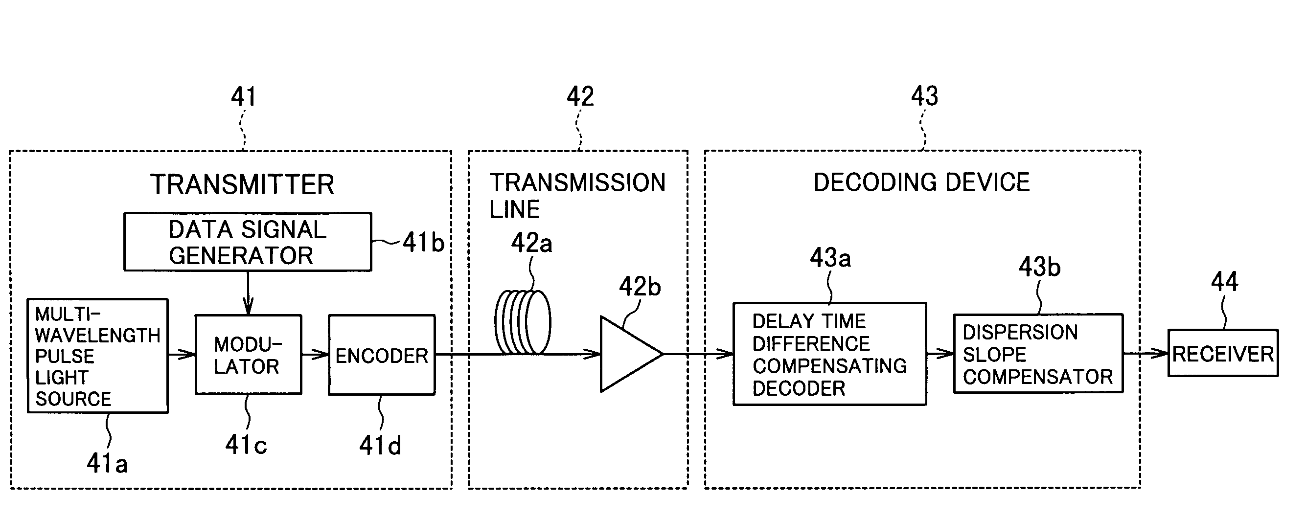
[0027]FIG. 3 is a block diagram showing the construction of an optical code division multiplexing communication system of the first embodiment (that is, a system capable of implementing an optical code division multiplexing communication method of the first embodiment) of the present invention. As shown in FIG. 3, the optical code division multiplexing communication system of the first embodiment includes a transmitter 41, a decoding device 43 connected to the transmitter 41 by a transmission line 42, and a receiver 44.

[0028]As shown in FIG. 3, the transmitter 41 includes a multi-wavelength optical pulse light source 41a for producing a wavelength multiplexing pulse, a data signal generator 41b, a wavelength multiplexing pulse modulator 41c which modulates a wavelength multiplexing pulse on the basis of a control signal from the data signal generator 41b, and an encoder which produces a multi-wavelength optical pulse train (for example, corresponding to optical pulses 31a, . . . , 3...

second embodiment

[0041]FIG. 8 is a block diagram showing the construction of an optical code division multiplexing communication system of the second embodiment (that is, a system capable of implementing an optical code division multiplexing communication method of the second embodiment) of the present invention. As shown in FIG. 8, the optical code division multiplexing communication system of the second embodiment is different, in that a dispersion slope compensator 51e is provided in the former stage of a transmission line 52, from the optical code division multiplexing communication system of the first embodiment in which the dispersion slope compensator (43b in FIG. 3) is provided in the latter stage of the transmission line (42 in FIG. 3).

[0042]A multi-wavelength pulse light source 51a, a data signal generator 51b, a modulator 51c, and an encoder 51d in FIG. 8 correspond to the multi-wavelength pulse light source 41a, the data signal generator 41b, the modulator 41c, and the encoder 41d in FIG...

third embodiment

[0046]FIG. 9 is a block diagram showing the construction of an optical code division multiplexing communication system of the third embodiment (that is, a system capable of implementing an optical code division multiplexing communication method of the third embodiment) of the present invention. As shown in FIG. 9, the optical code division multiplexing communication system of the third embodiment is different, in that a dispersion slope compensator 61e is provided in the former stage of a transmission line 62 and in that a dispersion slope compensator 63b is provided in the latter stage of the transmission line 62, from the optical code division multiplexing communication system of the first embodiment in which the dispersion slope compensator (43b in FIG. 3) is provided only in the latter stage of the transmission line (42 in FIG. 3).

[0047]A multi-wavelength pulse light source 61a, a data signal generator 61b, a modulator 61c, and an encoder 61d in FIG. 9 correspond to the multi-wa...


PUM


Abstract

An optical code division multiplexing communication method includes the steps of: producing a multi-wavelength optical pulse train from wavelength multiplexing pulse; transmitting the multi-wavelength optical pulse train through a transmission line using a time-spreading / wavelength-hopping method; decoding wavelength multiplexing pulse from the multi-wavelength optical pulse train transmitted through the transmission line; compensating delay time differences between individual optical pulses of the multi-wavelength optical pulse train, the delay time differences occurring in the step of transmitting the multi-wavelength optical pulse train through the transmission line; and compensating optical pulse spread in a time direction, which occurs in each of the optical pulses of the multi-wavelength optical pulse train in the step of transmitting the multi-wavelength optical pulse train through the transmission line.

Description

BACKGROUND OF THE INVENTION[0001]1. Field of the Invention[0002]The present invention relates to an optical code division multiplexing communication method using a time-spreading / wavelength-hopping code, an optical code division multiplexing communication system capable of implementing the optical code division multiplexing communication method, an encoding device constructing the optical code division multiplexing communication system, and a decoding device constructing the optical code division multiplexing communication system, and in particular, to chromatic dispersion compensation in optical code division multiplexing communication.[0003]2. Description of the Related Art[0004]FIG. 1 is a diagram for describing a principle of encoding and decoding in an optical code division multiplexing communication using a time-spreading / wavelength-hopping method. As shown in FIG. 1, an encoder 10 has a structure in which FBGs (Fiber Bragg Gratings) 10a, . . . , 10d of multiple wavelengths (f...

Claims


Application Information

Patent Timeline
Patent Type & Authority Patents(United States)
IPC IPC(8): H04J14/02H04B10/00H04B10/12H04B1/713H04B1/715H04B10/2507H04B10/2519H04B10/2525H04B10/524H04B10/556H04B10/572H04J14/00H04J14/04H04J14/06
CPCH04J14/005H04J14/00H04J14/02
Inventor NISHIKI, AKIHIKOSASAKI, KENSUKEKOBAYASHI, SHUKOKUTSUZAWA, SATOKO
Owner OKI ELECTRIC IND CO LTD
Features
  • R&D
  • Intellectual Property
  • Life Sciences
  • Materials
  • Tech Scout
  • Unparalleled Data Quality
  • Higher Quality Content
  • 60% Fewer Hallucinations
Learn More