
Board mounted memory card connector with EMI shield

Inactive Publication Date: 2006-02-23
MOLEX INC
View PDF9 Cites 12 Cited by
  • Summary
  • Abstract
  • Description
  • Claims
  • Application Information

AI Technical Summary

Benefits of technology

[0006] An object, therefore, of the invention is to provide a memory card connector of the character described, with improved EMI protection.

Problems solved by technology

Because of its high resistance, EMI protection is not as effective as is desired.

Method used


Image

  • Board mounted memory card connector with EMI shield
  • Board mounted memory card connector with EMI shield
  • Board mounted memory card connector with EMI shield

Examples


second embodiment

[0033]FIGS. 7 and 8 show the invention wherein leg portions 50b and feet portions 50c of ground shield cover 50 are on separate parts, generally designated 74, of the ground shield cover. The separate parts are connected together at connecting interfaces 76. Before the parts are connected, ground tabs 50e are subjected to a brush-plating process to form gold layers 72. By providing the separate parts, the cost of the electroplating process is decreased.

third embodiment

[0034] There are various ways that signal terminals 42 and ground terminals 44 can be electrically connected to printed circuit board 32. As stated above, adapter terminals 60 (FIG. 5) can be eliminated and the signal terminals and the ground terminals can be electrically connected directly to the printed circuit board. Accordingly, FIG. 9 shows a third embodiment wherein signal terminals 42 and ground terminals 44 extend all the way down through a plurality of slots 76 in connector portion 36 for direct connection to a plurality of signal circuit traces 78 and ground pads 64 on printed circuit board 32.

fourth embodiment

[0035] In a fourth embodiment shown in FIGS. 10 and 11, signal terminals 42 and ground terminals 44 have pin portions which project through a plurality of holes 80 in a pin alignment plate 82 and then into a plurality of holes 84 in an auxiliary circuit board 86. The pin portions of the terminals are soldered to appropriate circuit traces on the auxiliary circuit board, and the circuit traces on the auxiliary circuit board include a plurality of terminal portions 88 which engage appropriate terminals within a header connector 90 (FIG. 11) mounted on printed circuit board 32. Specifically, terminal portions 88 are deposited on an edge or tongue 86a of auxiliary circuit board 86, and the tongue is inserted into a slot 90a of the header connector to electrically connect signal terminals 42 and ground terminals 44 to the terminals within the header connector.


PUM


Abstract

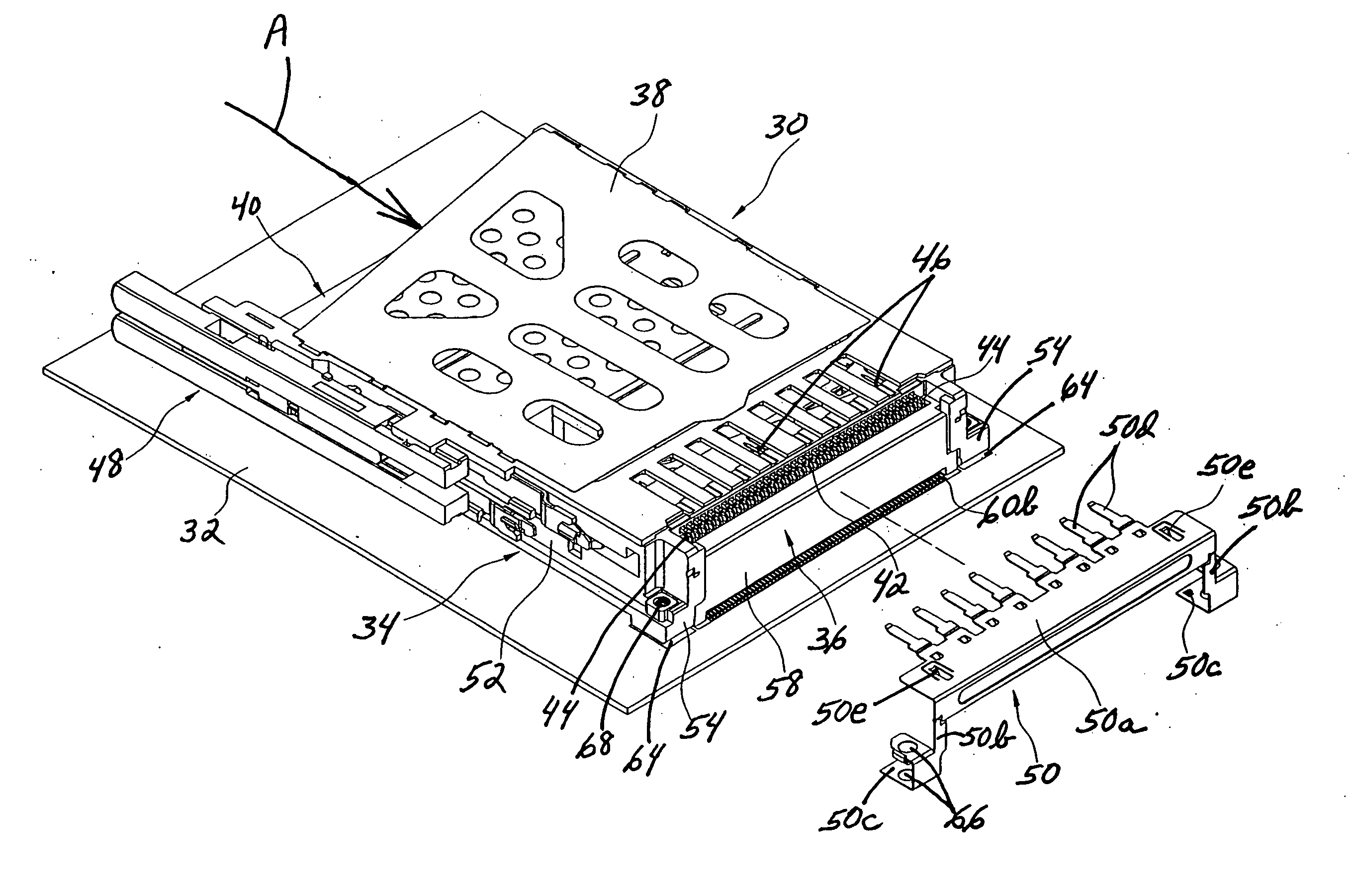
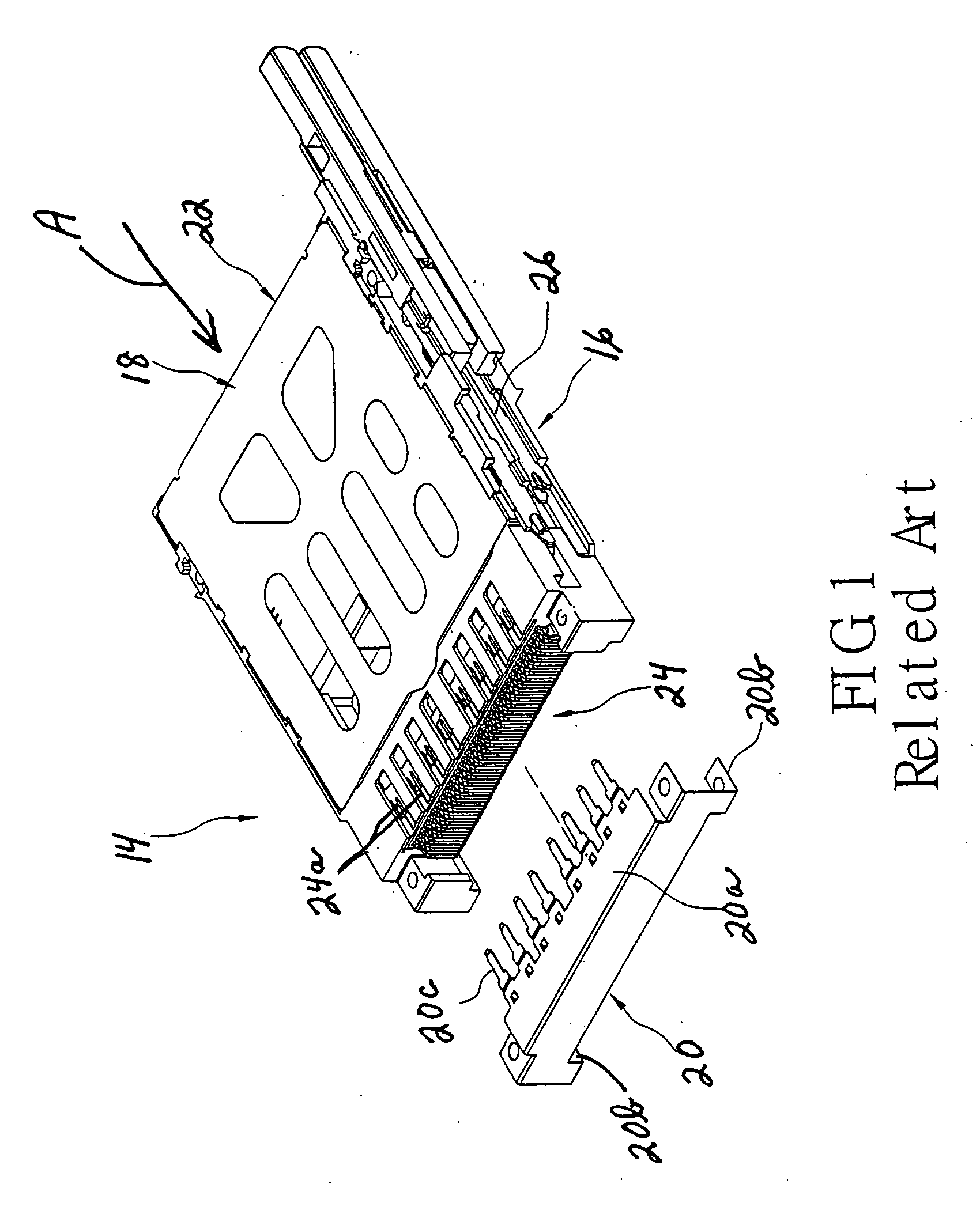
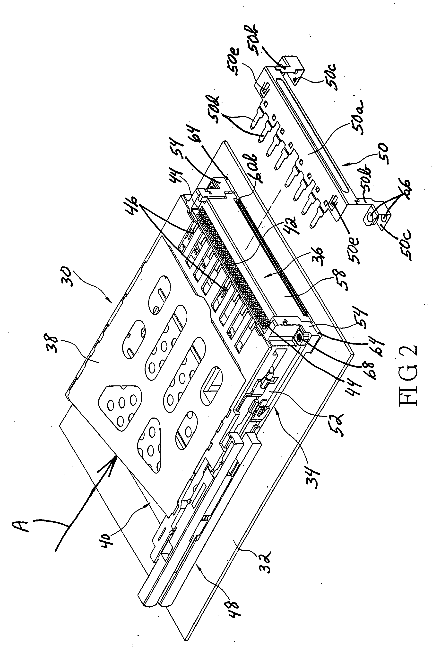
A memory card connector is provided for mounting on a printed circuit board. The connector includes an insulative housing having a rear terminal-mounting section and which, at least in part, defines a card-receiving space. A plurality of conductive signal terminals and at least one ground terminal are mounted on the rear section of the housing. The terminals are electrically connected to the printed circuit board and include contact portions for engaging appropriate contacts on the memory card when the card is inserted into the housing. A ground shield cover is mounted on the housing at the rear thereof for shielding at least major portions of the signal terminals. The ground shield cover is conductively coupled between the ground terminal and the printed circuit board.

Description

FIELD OF THE INVENTION [0001] This invention generally relates to the art of electrical connectors and, particularly, to a memory card connector for mounting on a printed circuit board and which has a ground shield cover over the termination area of the connector. BACKGROUND OF THE INVENTION [0002] Memory cards are known in the art and contain intelligence in the form of a memory circuit or other electronic program. Some form of card reader reads the information or memory stored on the card. Such cards are used in many applications in today's electronic society, including video cameras, digital still cameras, smart phones, PDA's, music players, ATMs, cable television decoders, toys, games, PC adapters, multi-media cards and other electronic applications. Typically, a memory card includes a contact or terminal array for connection through a card connector to a card reader system and then to external equipment. The connector readily accommodates insertion and removal of the card to pr...

Claims


Application Information

Patent Timeline
IPC IPC(8): H01R13/648H01R12/04H01R12/16H05K7/14
CPCH01R23/6873H01R12/716H05K7/1431H01R13/658
Inventor HO, YI-TSE
Owner MOLEX INC
Learn More