
Motorized ultrasonic scanhead

a scanhead and motorized technology, applied in the direction of catheters, sensors, reradiation, etc., can solve the problems of patient discomfort, present risks during manipulation, and significant discomfort to the patient, so as to minimize any electrical discharge associated, the effect of expanding the angle of vision and reducing the risk of manipulation

Active Publication Date: 2010-09-21
VERMON
View PDF16 Cites 22 Cited by
  • Summary
  • Abstract
  • Description
  • Claims
  • Application Information

AI Technical Summary

Benefits of technology

[0015]It is still another object of the present invention to provide a rotating linear array scanhead having improved EMI protection for transducer signals supplied to the external cables.
[0017]According to one aspect of the invention, there is provided a motorized ultrasonic scanhead device which is capable of providing rotation of an associated array transducer through an angle of 360° or more, so as to enable image acquisition for successive scanning planes being arranged around the principal axis of the device. The device of the invention can be implemented as part of, i.e., can be incorporated in, endoscopes (e.g., transesophageal endoscopes), laparoscopes, endocavity or intracavity probes so as to provide an expanded angle of vision or to render 3D images without the need for external movement of the device. A further aspect of this invention concerns a motorized scanhead wherein the motorization means or motor is isolated from transducer signal interconnections in order to minimize any electrical discharges associated with motor operations and to also provide more room for the assembly between the probe housing and the scanhead device.

Problems solved by technology

However, such rotation of the probe may cause significant discomfort to the patient and present risks during manipulation.
However, as long as the rigid tube provides sheathing externally if the endoscope, any movement of the transducer will be directly communicated to the external medium and this can lead to patient discomfort and a risk of wounding or other damage to the organ in contact with the probe.
Further, sealing problems and problems with disinfection of the instrument may also occur with the use of seals.
The movement of the transducer only affects the articulated portion of the probe apparatus, thus decreasing patient discomfort and the risk of injury to the tissue.
However, the devices of both patents discussed above still suffer drawbacks and disadvantages.
The latter include, for example, the interdependence between the articulation mechanism and the rotation of the transducer (and the corresponding variation of resistance torsion stiffness versus the angle of articulation), the inaccuracy induced by movement of the transducer combined with the effect of friction, and the lack of compatibility with precision 3D acquisition or real time volume image rendering.
It is therefore apparent that this approach cannot be practically applied to devices that include an array transducer wherein hundreds of transducer interconnections are required.
Further, there is a risk of liquid leakage through the motor shaft and this makes such an apparatus unreliable for use in continuous operation (as is required in 3D rendering operations).
However, the approach disclosed in this patent suffers at least two major limitations.
First, the transducer cannot perform a complete rotation (because of the interconnection cables).
Second, the rotation velocity of the transducer will be significantly slowed by the liquid resistance of the coupling liquid used in this type of transducer.
This results in a need for dynamic seals for protection of the motor, and such seals often exhibit a lack of reliability and durability.
This positioning does not permit the assembly of linear arrays due to the lack of room in the lateral dimension.
Thus, this approach is not suitable for use in volume acquisition modalities.
This method results in non-uniform angular velocity so that the rotational speed must be corrected by a position sensor co-located with the transducer as well as dedicated servo-control electronics to ensure precise positioning of the transducer when rotated.

Method used


Image

  • Motorized ultrasonic scanhead
  • Motorized ultrasonic scanhead
  • Motorized ultrasonic scanhead

Examples


Embodiment Construction

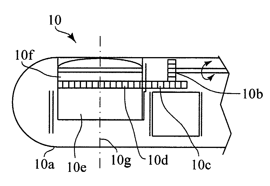
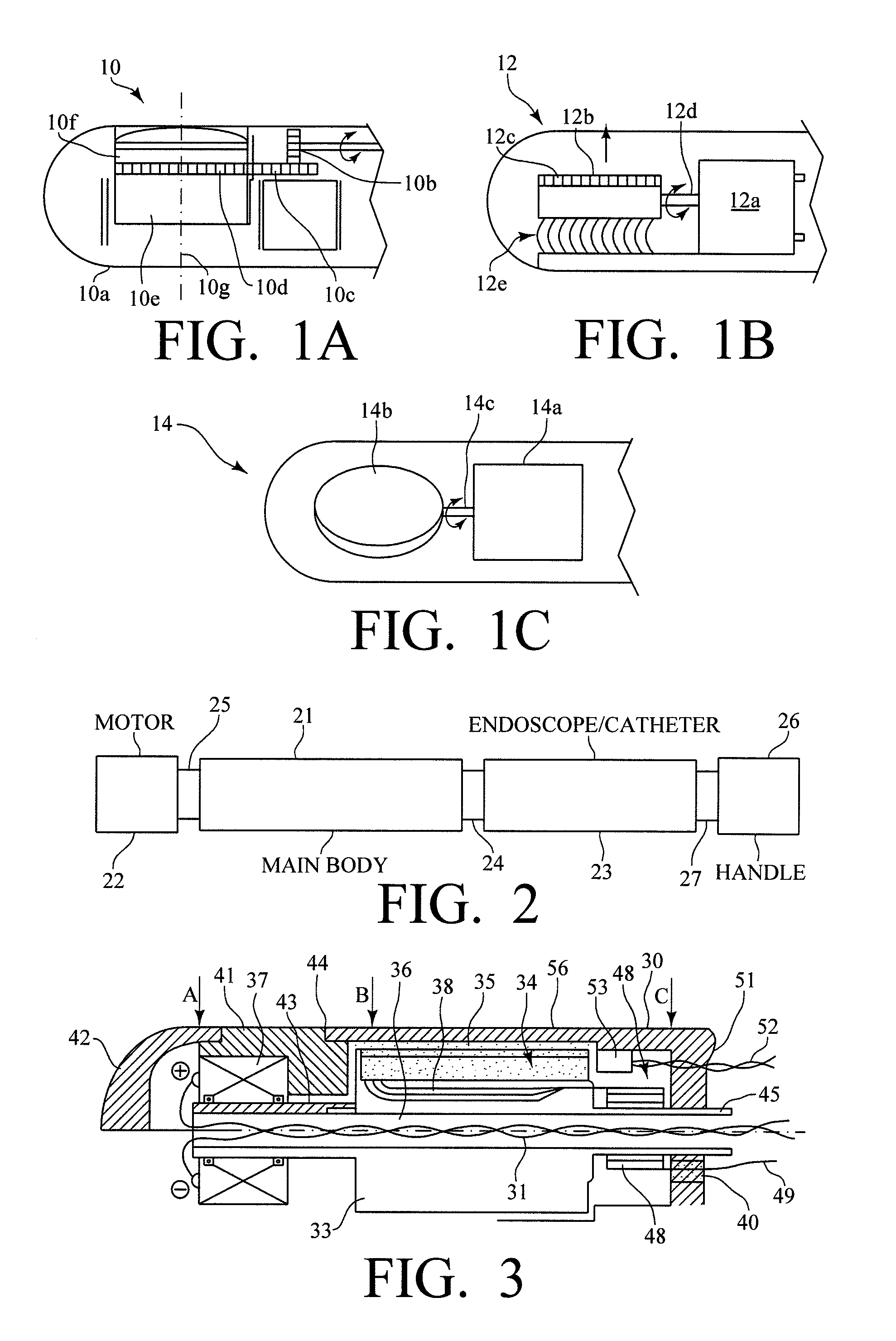
[0035]Before considering the preferred embodiments of the present invention, reference is made to FIGS. 1(a), 1(b) and 1(c), which show various approaches or modes for providing rotational movement of a transducer in an ultrasonic scanhead, all of which use either a remotely located motor or a motor directly coupled to the transducer to be rotated.

[0036]Referring to FIG. 1(a), there is shown a schematic cross-sectional first prior art probe 10 including a probe body 10a containing a motor-driven drive gear 10b that drives an intermediate gear 10c that, in turn, drives ring gear 10d mounted on a rotatable transducer unit 10e so as to extend around the circumference thereof. Transducer unit 10e is of conventional construction including a transducer array 10f and is mounted such that the longitudinal axis 10g thereof extends orthogonal to the longitudinal axis of the probe 10. The drive mechanism including gears 10b, 10c and 10d converts rotation of drive gear 10b into rotation of tran...


PUM


Abstract

A motorized scanhead device is capable of rotating an array transducer through 360 degrees of angular rotation in a manner such as to provide acquisition of images in successive scanning planes arranged around the principal axis of the device. The device can be incorporated in endoscopes (e.g., transesophageal endoscopes), laparoscopes, endocavity or intracavity probes so as to provide an expanded angle of vision or to render 3D images, without the need for external movement of the device. The motorized scanhead device includes a motor that is isolated from the transducer signal interconnections in order to minimize electrical discharges associated with motor operation and to provide more room between an associated probe housing and the scanhead device.

Description

FIELD OF THE INVENTION[0001]This invention relates to ultrasonic diagnostic scanheads and, more particularly, to a motorized scanhead device capable of rotating an array transducer through 360 degrees of rotation to provide image acquisition.DESCRIPTION OF THE RELATED ART[0002]Ultrasonic imaging apparatus dedicated to endocavity or intracavity operations are well known especially in diagnostic applications such as celioscopy, TE Transesophageal Echography, laparoscopy, and transvaginal and transrectal applications. In addition, probes for intraluminal or intravascular use are very similar except for their smaller diameter. All of these apparatus has a common characteristic, viz., an ultrasonic scanhead is assembled at the distal tip of the probe so as to allow imaging of regions of the tissue being examined which are located remotely and cannot be directly accessed.[0003]With respect to the endocavity modalities currently being practiced, the existing apparatus are typically provide...

Claims


Application Information

Patent Timeline
Patent Type & Authority Patents(United States)
IPC IPC(8): A61B8/14
CPCA61B8/12A61B8/445A61B8/4461A61B8/4281
Inventor FLESCH, AIMENGUYEN-DINH, AN
Owner VERMON
Learn More