
Apparatus and process for reducing the susceptability of active implantable medical devices to medical procedures such as magnetic resonance imaging

a technology of active implantable medical devices and apparatus, applied in the direction of feed-through capacitors, cell components, therapy, etc., to achieve the effect of increasing the impedance of leadwires, reducing the saturation of magnetic flux cores of lossy, and increasing the emi protection of aimd electronics

Inactive Publication Date: 2010-07-27
GREATBATCH SIERRA INC
View PDF66 Cites 174 Cited by
  • Summary
  • Abstract
  • Description
  • Claims
  • Application Information

AI Technical Summary

Benefits of technology

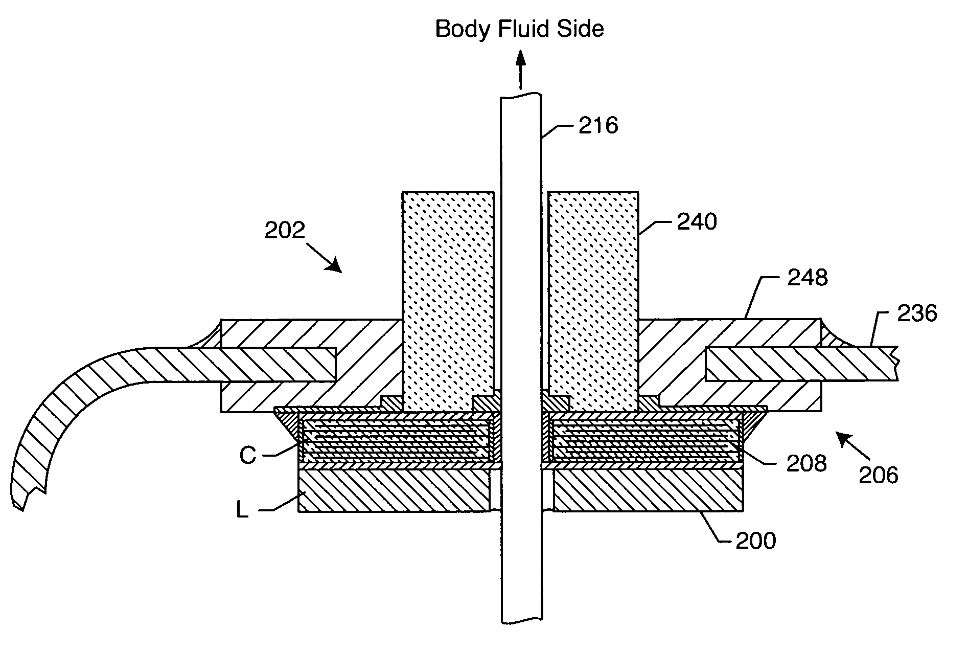
[0025]The present invention resides in a feedthrough terminal assembly for an active implantable medical device (AIMD) including a plurality of leadwires extending from electronic circuitry of the AIMD, and a lossy ferrite inductor through which the leadwires extend in non-conductive relation for increasing the impedance of the leadwires at selected RF frequencies and reducing magnetic flux core saturation of the lossy ferrite inductor through phase cancellation of signals carried by the leadwires. The present invention also resides in a process for filtering electromagnetic interference (EMI) in an implanted leadwire extending from an active implantable medical device (AIMD) into body fluids or tissue, wherein the leadwire is subjected to occasional high-power electromagnetic fields such as those produced by medical diagnostic equipment including magnetic resonance imaging. In the process of the present invention, the leadwire is passed through an inductive and resistive low pass filter element to increase EMI protection of AIMD electronics and to raise the output impedance of the AIMD circuitry thereby reducing currents induced in the implanted leadwire by the occasional high-power electromagnetic fields, wherein the low pass filter element has a diameter-to-thickness ratio of at least 1:1.
[0042]Moreover, a process is provided for filtering the electromagnetic signals in a plurality of leadwires extending from an active implantable medical device into body fluids or tissue, wherein the leadwires are subjected to occasional high-power electromagnetic fields or signals generated by AIMD circuitry or external sources such as medical diagnostic equipment including magnetic resonance imaging (MRI). The steps comprise conductively coupling the leadwires to respective sets of electrode plates within a feedthrough capacitor optimized for electromagnetic interference (EMI) filtering, and passing the leadwires through a common inductive element disposed adjacent to the feedthrough capacitor and between the AIMD circuitry and the feedthrough capacitor, for decoupling signals induced on the leadwires by the occasional high-power electromagnetic fields or signals generated by AIMD circuitry or external sources, from the feedthrough capacitor, to protect AIMD circuitry from ring-back of energy from the feedthrough capacitor induced by the occasional high-power electromagnetic fields or signals.

Problems solved by technology

Compatibility of cardiac pacemakers, implantable defibrillators and other types of active implantable medical devices with magnetic resonance imaging (MRI) and other types of hospital diagnostic equipment has become a major issue.
There have been reports of latent problems with cardiac pacemakers after an MRI procedure occurring many days later.
The lossy ferrite inductor or toroidal slab concept as described herein is not intended to provide protection against static magnetic fields such as those produced by magnetic resonance imaging.
Unfortunately, these leadwires can act as an antenna to collect stray electromagnetic interference (EMI) signals for transmission via the terminal pins into the interior of the medical device.
Such unwanted EMI signals can disrupt proper operation of the medical device, resulting in malfunction or failure.
For example, it has been documented that stray EMI signals emanating from cellular telephones can inhibit pacemaker operation, resulting in asynchronous pacing, tracking and missed beats.
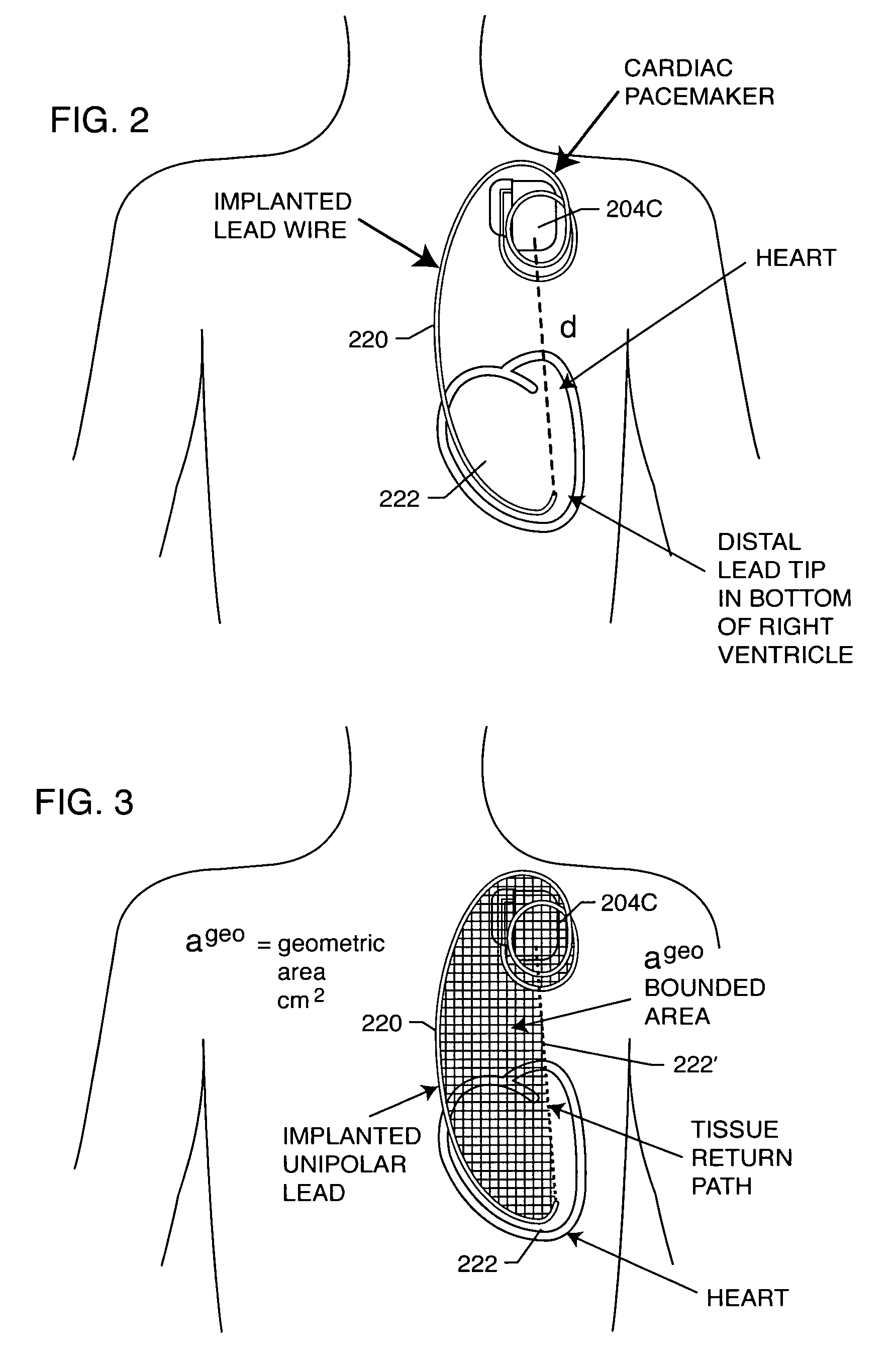
However, when a pacemaker leadwire system is exposed to a powerful time varying electromagnetic field, such as induced by MRI, the last thing that is desirable is to create a low impedance in the leadwire system.
These antennas are not very efficient due to the damping effects of body tissue; however, this can often be offset by body resonances.
(1) Closure of the pacemaker reed switch. When a pacemaker is brought close to the MRI scanner, the reed switch can close, which puts the pacemaker into a fixed rate or asynchronous pacing mode. Asynchronous pacing may compete with the patient's underlying cardiac rhythm. This is one reason why patients have generally been advised not to undergo MRI. Fixed rate or asynchronous pacing for most patients is not an issue. However, in patients with unstable conditions, such as myocardial ischemia, there is a substantial risk for ventricular fibrillation during asynchronous pacing. In most modern pacemakers the magnetic reed switch function is programmable. If the magnetic reed switch response is switched off, then synchronous pacing is still possible even in strong magnetic fields. The possibility to open and re-close the reed switch in the main magnetic field by the gradient field cannot be excluded. However, it is generally felt that the reed switch will remain closed due to the powerful static magnetic field. It is theoretically possible for certain reed switch orientations at the gradient field to be capable of repeatedly closing and re-opening the reed switch.
(2) Reed switch damage. Direct damage to the reed switch is theoretically possible, but has not been reported in any of the known literature. In an article written by Roger Christoph Luchinger of Zurich, he reports on testing in which reed switches were exposed to the static magnetic field of MRI equipment. After extended exposure to these static magnetic fields, the reed switches functioned normally at close to the same field strength as before the test.
(3) Pacemaker displacement. Some parts of pacemakers, such as the batteries and reed switch, contain ferrous magnetic materials and are thus subject to mechanical forces during MRI. Pacemaker displacement may occur in response to magnetic force or magnetic torque.
(4) Radio frequency field. At the frequencies of interest in MRI, RF energy can be absorbed and converted to heat. The power deposited by RF pulses during MRI is complex and is dependent upon the power and duration of the RF pulse, the transmitted frequency, the number of RF pulses applied per unit time, and the type of configuration of the RF transmitter coil used. The amount of heating also depends upon the volume of tissue imaged, the electrical resistivity of tissue and the configuration of the anatomical region imaged. The cause of heating in an MRI environment is two fold: (a) RF field coupling to the lead can occur which induces significant local heating; and (b) currents induced during the RF transmission can cause local Ohms Law heating next to the distal TIP electrode of the implanted lead. The RF field in an MRI scanner can produce enough energy to induce leadwire currents sufficient to destroy some of the adjacent myocardial tissue. Various ablation has also been observed. The effects of this heating are not readily detectable by monitoring during the MRI. Indications that heating has occurred would include an increase in pacing threshold, myocardial perforation and lead penetration, or even arrhythmias caused by scar tissue. Such long term heating effects of MRI have not been well studied yet.
(5) Alterations of pacing rate due to the applied radio frequency field. It has been observed that the RF field may induce undesirable fast pacing (QRS complex) rates. There are two mechanisms which have been proposed to explain rapid pacing: direct interference with pacemaker electronics or pacemaker reprogramming (or reset). In both of these cases, it would be desirable to raise the impedance, make the feedthrough capacitor more effective and provide a very high degree of protection to AIMD electronics. This will make alterations in pacemaker pacing rate and / or pacemaker reprogramming much more unlikely.
(6) Time-varying magnetic gradient fields. The contribution of the time-varying gradient to the total strength of the MRI magnetic field is negligible, however, pacemaker systems could be affected because these fields are rapidly applied and removed. The time rate of change of the magnetic field is directly related to how much electromagnetic force and hence current can be induced into a leadwire system. Luchinger reports that even using today's gradient systems with a time-varying field up to 50 Tesla per second, the induced currents are likely to stay below the biological thresholds for cardiac fibrillation. A theoretical upper limit for the induced voltage by the time-varying magnetic gradient field is 20 volts. Such a voltage during more than 0.1 milliseconds could be enough energy to directly pace the heart.
Currents induced by time-varying magnetic gradient fields may lead to local heating.
There are additional problems possible with implantable cardioverter defibrillators (ICDs).
ICDs use different and larger batteries which could cause higher magnetic forces.
The programmable sensitivity in ICDs is normally much higher than it is for pacemakers, therefore, ICDs may falsely detect a ventricular tachyarrhythmia and inappropriately deliver therapy.
There can also be heating problems of ICD leads which are expected to be comparable to those of pacemaker leads.
In summary, there are a number of studies that have shown that MRI patients with active implantable medical devices, such as cardiac pacemakers, can be at risk for potential hazardous effects.
Further complicating this is the fact that each manufacturer's pacemaker and ICD designs behave differently.
Most experts still conclude that MRI for the pacemaker patient should not be considered safe.
As MRI technology progresses, including higher field gradient changes over time applied to thinner tissue slices at more rapid imagery, the situation will continue to evolve and become more complex.
With the patient's life literally at risk, the physician may make the decision to perform MRI in spite of all of the previously described attendant risks to the pacemaker system.

Method used


Image

  • Apparatus and process for reducing the susceptability of active implantable medical devices to medical procedures such as magnetic resonance imaging
  • Apparatus and process for reducing the susceptability of active implantable medical devices to medical procedures such as magnetic resonance imaging
  • Apparatus and process for reducing the susceptability of active implantable medical devices to medical procedures such as magnetic resonance imaging

Examples


Embodiment Construction

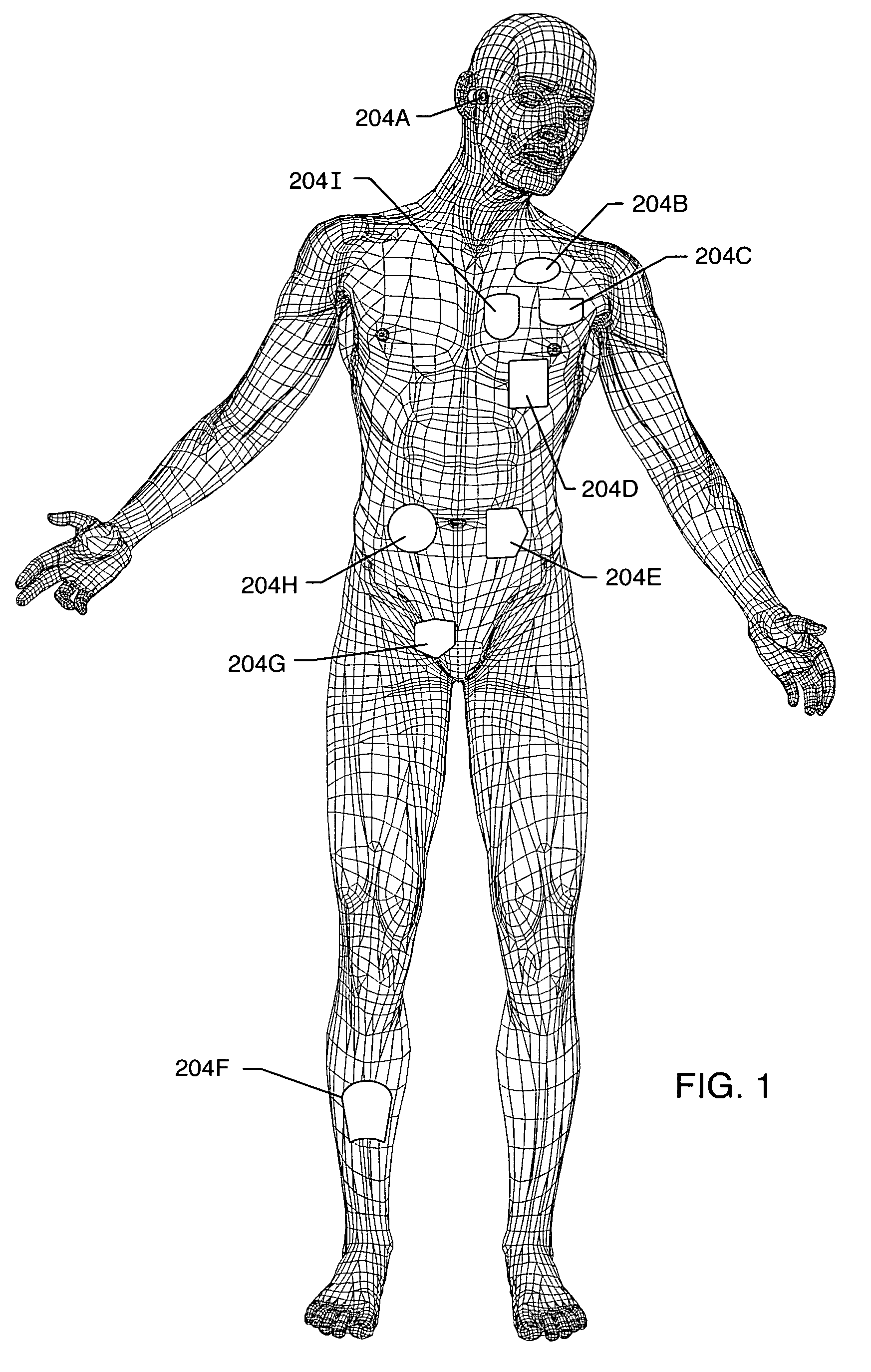
[0185]As shown in the drawings for purposes of illustration, the present invention relates to a lossy ferrite inductor with both resistive and inductive properties 200 (hereinafter referred to as “lossy ferrite inductor”), which is installed in proximity or adjacent to the hermetic terminal 202 of an active implantable medical device (AIMD) 204. The lossy ferrite inductor 200 can be combined with a feedthrough filter capacitor assembly 206 which includes a capacitor 208 having first and second sets of conductive electrode plates 210, 212 embedded within an insulative or dielectric body 214, which is mounted to the hermetic terminal 202 of the implantable medical device 204. At least one feedthrough terminal pin or leadwire 216 extends through the lossy ferrite inductor 200 in non-conductive relation. When used in combination with a feedthrough capacitor 208, the feedthrough terminal pin 216 extends through the capacitor in conductive relation with the first set of electrode plates 2...


PUM


Abstract

A feedthrough terminal assembly for an active implantable medical device (AIMD) includes a plurality of leadwires extending from electronic circuitry of the AIMD, and a lossy ferrite inductor through which the leadwires extend in non-conductive relation for increasing the impedance of the leadwires at selected RF frequencies and reducing magnetic flux core saturation of the lossy ferrite inductor through phase cancellation of signals carried by the leadwires. A process is also provided for filtering electromagnetic interference (EMI) in an implanted leadwire extending from an AIMD into body fluids or tissue, wherein the leadwire is subjected to occasional high-power electromagnetic fields such as those produced by medical diagnostic equipment including magnetic resonance imaging.

Description

RELATED APPLICATIONS[0001]This is a Continuation-in-Part of U.S. patent application Ser. No. 10 / 825,900 filed on Apr. 15, 2004, now U.S. Pat. No. 6,999,818 the contents of which are incorporated herein by reference. This is also a Continuation-in-Part of U.S. patent application Ser. No. 10 / 842,967, filed May 10, 2004 now U.S. Pat. No. 7,038,900. This application is also a Continuation-in-Part of U.S. patent application Ser. No. 10 / 778,954, filed Feb. 12, 2004 now U.S. Pat. No. 6,985,347. This application also claims priority from U.S. Provisional Application Ser. No. 60 / 607,276, filed Sep. 2, 2004.BACKGROUND OF THE INVENTION[0002]This invention relates generally to EMI filter assemblies, particularly of the type used in active implantable medical devices (AIMDs) such as cardiac pacemakers, cardioverter defibrillators and the like, which decouple and shield internal electronic components of the medical device from undesirable electromagnetic interference (EMI) signals.[0003]Compatibi...

Claims


Application Information

Patent Timeline
Patent Type & Authority Patents(United States)
IPC IPC(8): A61N1/375A61N1/37H01G4/35H03H1/00
CPCA61N1/37A61N1/3754H01F17/06H01G4/35A61N1/3718A61N2001/086H01F2017/065H01F2017/067H03H2001/0042H03H2001/0057A61N1/086
Inventor STEVENSON, ROBERT A.
Owner GREATBATCH SIERRA INC
Learn More