
Methods of clock throttling in an integrated circuit

a technology of integrated circuits and clocks, applied in the direction of liquid/fluent solid measurement, instruments, sustainable buildings, etc., can solve the problems of catastrophic failure requiring component replacement, not necessarily true instantaneously, and reducing performan

Inactive Publication Date: 2006-02-23
INTEL CORP
View PDF21 Cites 84 Cited by
  • Summary
  • Abstract
  • Description
  • Claims
  • Application Information

AI Technical Summary

Benefits of technology

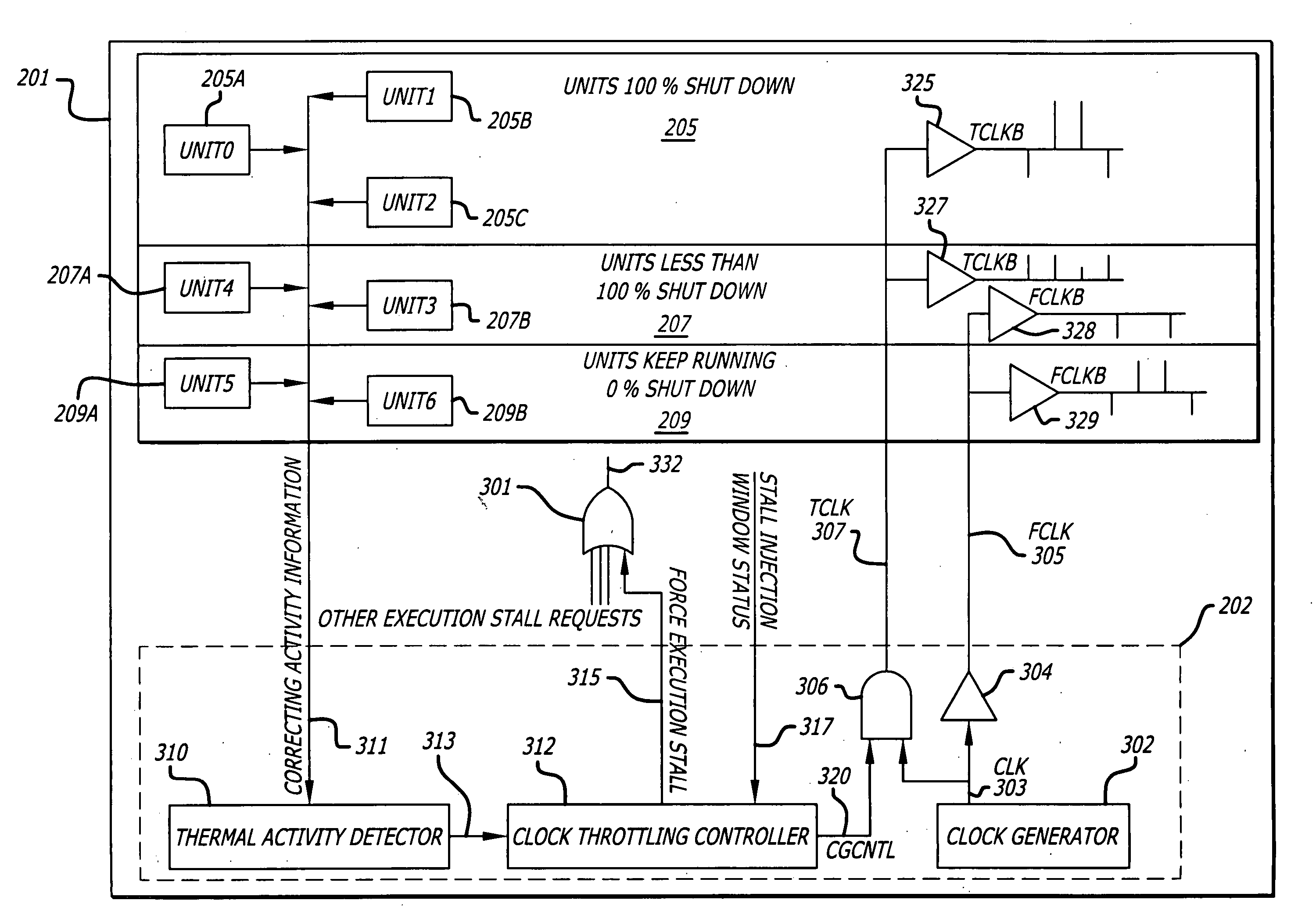
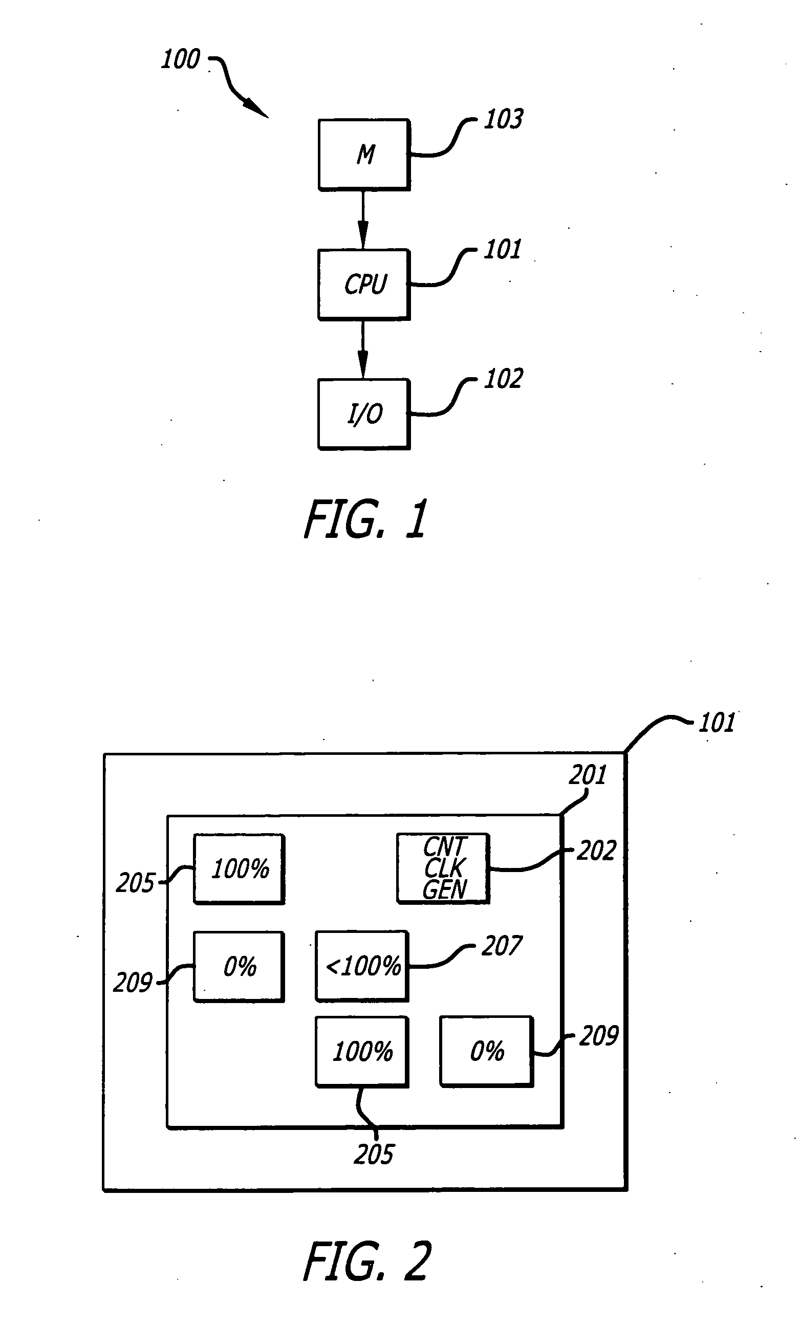
The present invention relates to thermal management of integrated circuits and in particular to the use of digital thermal throttling of clocks to control the temperature of the circuitry. The invention provides a method for safely throttling clocks in a processor to minimize di / dt variations and avoid large power consumption spikes during clock shut down and starting up. The invention accumulates the localized functional activity of functional blocks in an integrated circuit to determine a measure of global functional activity and then determines whether or not the measure exceeds a thermal activity limit of the integrated circuit. If so, the integrated circuit is forced into an execution stall where the clock is gradually turned off or stopped in circuitry to avoid large di / dt variations. The invention provides a gradual throttling of the clock and a controlled change in the ratio of the throttled clock frequency to the free running clock frequency to avoid large di / dt variations during clock shut down and starting up. The technical effect of the invention is to improve the thermal management of integrated circuits and minimize the impact of heat on performance and reliability.

Problems solved by technology

Heat in electronic circuitry if not dissipated sufficiently enough can reduce performance, cause soft errors, and in a worst case—result in catastrophic failure requiring replacement of components.
While this may be true over an average, it is not necessarily true instantaneously.
In some cases when a clock is abruptly stopped to circuitry, the heat generated actually increases causing the thermal temperature of the integrated circuitry to rise.

Method used


Image

  • Methods of clock throttling in an integrated circuit
  • Methods of clock throttling in an integrated circuit
  • Methods of clock throttling in an integrated circuit

Examples


Embodiment Construction

[0016] In the following detailed description of the present invention, numerous specific details are set forth in order to provide a thorough understanding of the present invention. However, it will be obvious to one skilled in the art that the present invention may be practiced without these specific details. In other instances well known methods, procedures, components, and circuits have not been described in detail so as not to unnecessarily obscure aspects of the present invention.

[0017] Thermal throttling allows a processor to cool down in trade for performance. The most common technique to thermally throttle a processor is to stop the internal clock. In some cases, suddenly stopping the internal clock to circuitry results in a di / dt variation where the current instantaneously spikes which can lead to even greater power consumption and thermal increases. Advanced chip process technologies using lower voltage supplies, dynamic circuit designs, and higher clock frequencies make ...


PUM


Abstract

Thermal throttling control to safely throttle clocks OFF and ON in an integrated circuit. Digital thermal throttling control is provided to gradually throttle a clock's frequency from ON to OFF and from OFF to ON. The gradual throttling can minimize an instantaneous current rise that would otherwise occur with a rapid shut OFF and a rapid turn ON of a clock. Included are methods and apparatus for digital thermal throttle control in an integrated circuit.

Description

CROSS REFERENCE TO RELATED APPLICATIONS [0001] This application claims the benefit and is a continuation of U.S. patent application Ser. No. 09 / 749,088, filed Dec. 26, 2000 by Mitsuhiro Adachi, entitled METHOD AND APPARATUS FOR THERMAL THROTTLING OF CLOCKS, now allowed.FIELD OF THE INVENTION [0002] The present invention relates generally to the field of thermal management of integrated circuits. Particularly, the present invention relates to thermal management circuits which throttle clocks of an integrated circuit to control its temperature. BACKGROUND OF THE INVENTION [0003] Heat in electronic circuitry if not dissipated sufficiently enough can reduce performance, cause soft errors, and in a worst case—result in catastrophic failure requiring replacement of components. The heat generated by electronic circuitry is a direct function of clock frequency. Temperature, a measure of heat, is proportional to power consumption which in turn is proportional to operational frequency. In ord...

Claims


Application Information

Patent Timeline
Patent Type & Authority Applications(United States)
IPC IPC(8): G06F1/26G06F1/20G06F1/32
CPCG06F1/206G06F1/3203Y02B60/1275Y02B60/1217Y02B60/1221G06F1/3237Y02D10/00
Inventor ADACHI, MITSUHIRO
Owner INTEL CORP
Learn More