Hydrostatic transaxle and hydraulically driven vehicle

a transaxle and hydraulic drive technology, applied in mechanical equipment, non-deflectable wheel steering, transportation and packaging, etc., can solve the problems of large operation force of the link mechanism, small operation efficiency, and complicated link mechanism for moving the two movable swash plates according to the turning of the steerable wheels. , to achieve the effect of simple and compact link

Active Publication Date: 2006-03-02
KANZAKI KOKYUKOKI MFG
View PDF7 Cites 28 Cited by
  • Summary
  • Abstract
  • Description
  • Claims
  • Application Information

AI Technical Summary

Benefits of technology

[0008] A first object of the present invention is to provide a hydrostatic transaxle supporting a pair of left and right steerable drive wheels and comprising a pair of hydraulic motors for driv...

Problems solved by technology

However, the link mechanism for moving the two movable swash plates according to the turning of the steerable wheels is complicated, and expanded so as to reduce spaces for other parts.
Further, the link mechanism requires a large operation force because of its small operational efficiency.
However, there is a problem that the peripheral speed of the drive wheel may be unexpectedly reduced because of bad road condition so as to be slower than that corresponding to the amount of fluid flowing through the corr...

Method used


Image

  • Hydrostatic transaxle and hydraulically driven vehicle
  • Hydrostatic transaxle and hydraulically driven vehicle
  • Hydrostatic transaxle and hydraulically driven vehicle

Examples


first embodiment

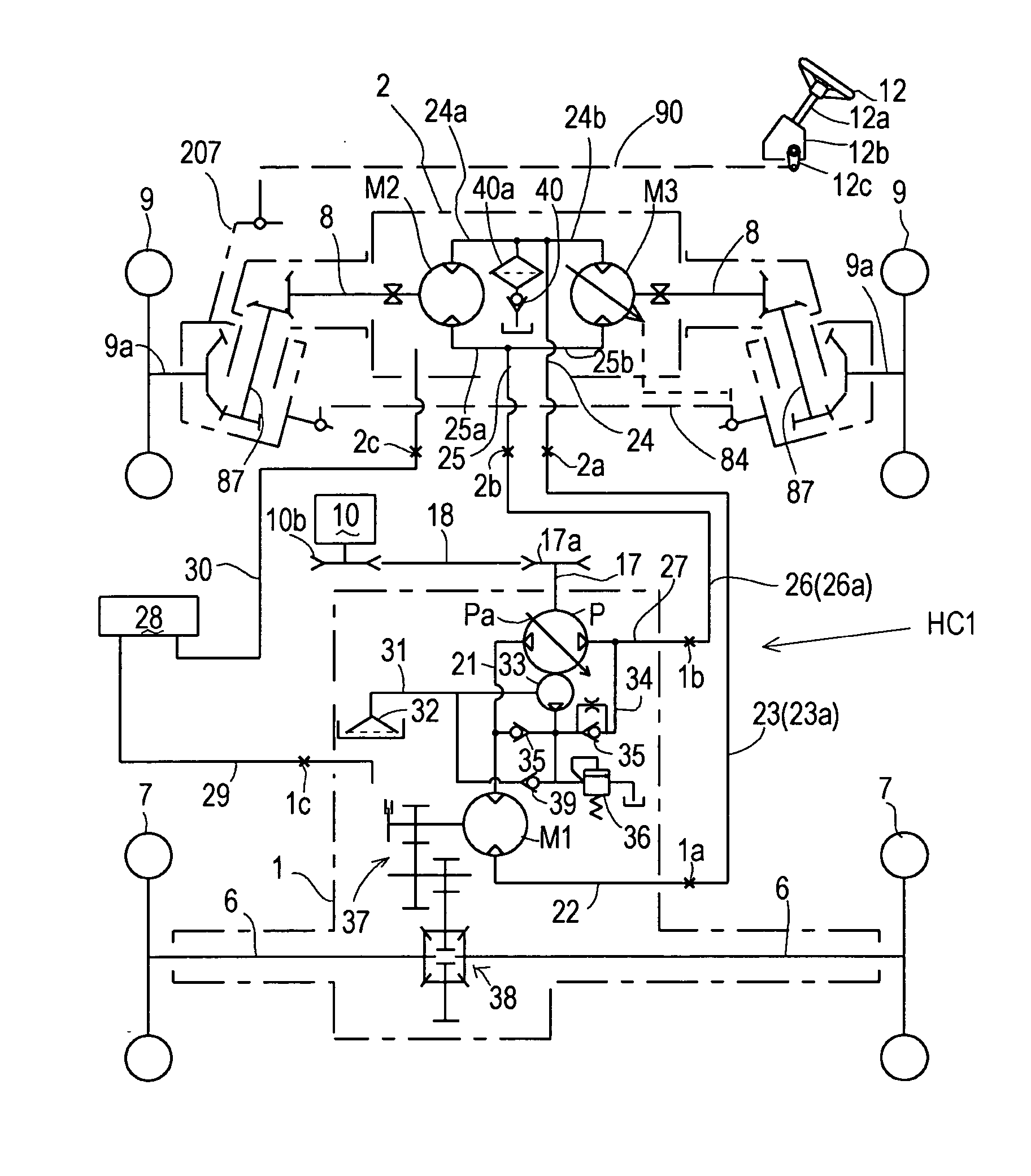
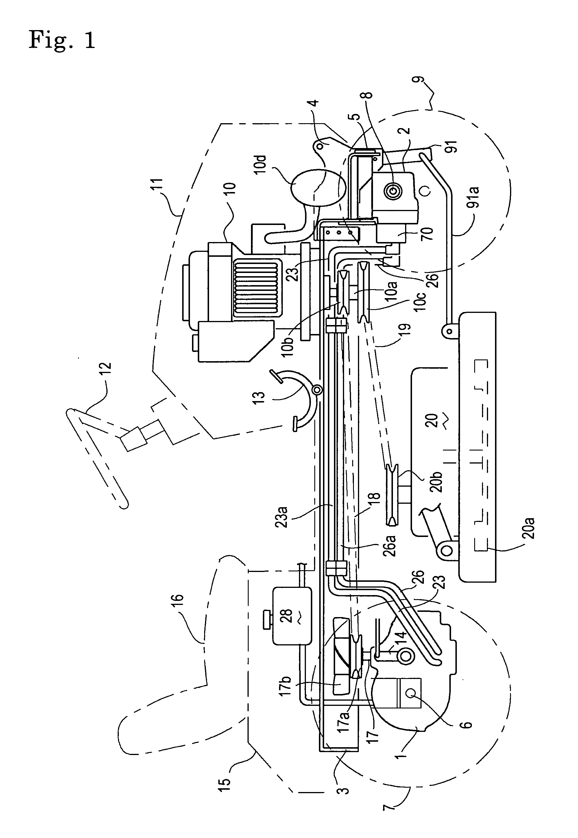
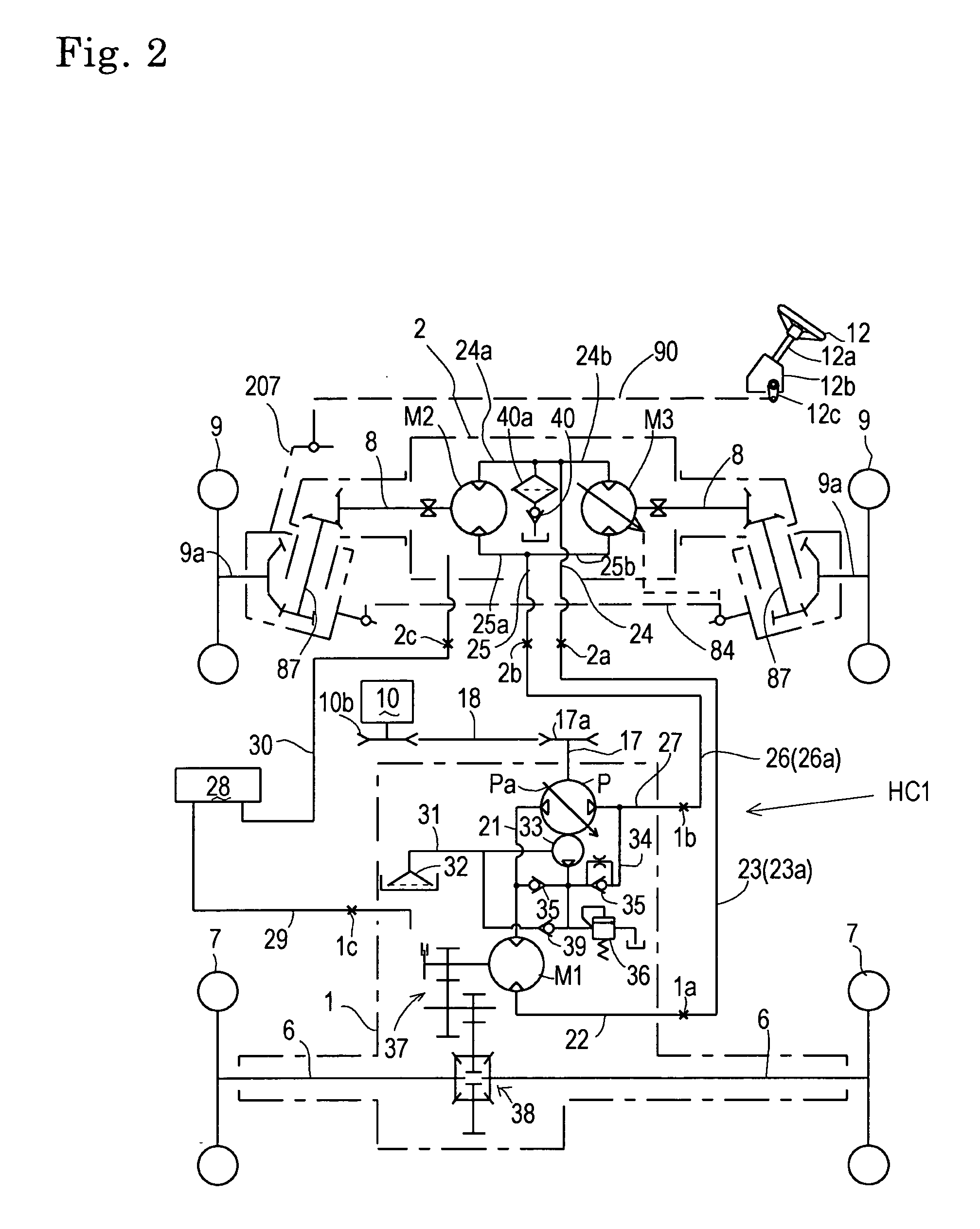
[0060] Referring to FIGS. 1 and 2, description will be given of a lawn tractor employing an Ackerman type front wheel steering system, serving as a hydraulically driven four-wheel drive vehicle according to the present invention. The lawn tractor has a vehicle frame 3, which supports a rear transaxle 1 below a front portion thereof. A bracket 4 is fixed onto a front bottom portion of vehicle frame 3. A front transaxle 2 is suspended from bracket 4 via a fore-and-aft horizontal center pin 5 so that left and right ends of front transaxle 2 are vertically swingable. Rear transaxle 1 journals left and right opposite axles 6, which project laterally outward from rear transaxle 1 so as to be fixed at outer ends thereof to respective center portions of rear wheels 7. Front transaxle 2 journals left and right opposite axles 8, which project laterally outward from front transaxle 2 so as to be steerably and drivingly connected at outer ends thereof to respective center portions of front whee...

second embodiment

[0083] Referring to FIGS. 4, 5 and 6, an Ackerman-type steering lawn tractor serving as a four-wheel drive vehicle equipped with a hydraulic transaxle according to the present invention will be described. The lawn tractor has vehicle frame 3 supporting a rear transaxle 101 at a rear portion thereof, and front transaxle 2 at a front portion thereof. A pump unit 50 and reservoir tank 28 are laterally juxtaposed and supported by vehicle frame 3 just in front of rear transaxle 101. Preferably, similar to the vehicle of FIG. 1, the present vehicle includes bracket 4 fixed on a front end portion of vehicle frame 3, and fore-and-aft horizontal center pin 5 pivoted on bracket 4 for rotatably suspending front transaxle 2 therefrom. Rear transaxle 101 supports left and right axles 6 whose outer ends are fixed to the center portions of respective rear wheels 7 (alternatively, steerably connected to respective rear wheels 7, as discussed later). Front transaxle 2 supports left and right axles 8...


PUM


Abstract

A hydrostatic transaxle, comprises: a transaxle casing; a pair of left and right axles disposed in the transaxle casing; a pair of hydraulic motors for driving the respective axles; and a pair of left and right steerable drive wheels disposed on left and right outsides of the transaxle casing so as to be drivingly connected to the respective axles. The hydraulic motors are disposed in the housing so as to be fluidly connected to a common hydraulic pressure source in parallel to each other. One of the hydraulic motors is a fixed displacement hydraulic motor, and the other is a variable displacement hydraulic motor. Displacement of the variable displacement hydraulic motor is changed according to change of steered angles of the drive wheels.

Description

BACKGROUND OF THE INVENTION [0001] 1. Field of the Invention [0002] The present invention relates to a hydrostatic transaxle, which supports a pair of left and right steerable drive wheels, and incorporates a pair of hydraulic motors for driving the respective drive wheels. Further, the present invention relates to a hydraulically driven vehicle, which comprises a common hydraulic pressure source and at least two hydraulic motors connected in series to the common hydraulic pressure source, wherein one of the at least two hydraulic motors drives front drive wheels (or a front drive wheel), and the other drives rear drive wheels (or a rear drive wheel). [0003] 2. Related Art [0004] Conventionally, as disclosed in International Publication WO 2004 / 062956, there is a well-known hydraulically driven vehicle having a main transaxle and an auxiliary transaxle. The main transaxle supports main drive wheels, and comprises a hydraulic motor for driving the main drive wheels. The auxiliary tra...

Claims


Application Information

Patent Timeline
IPC IPC(8): B62D11/02A01B69/00A01D34/64B60K17/10F16H61/4131F16H61/4139F16H61/4148F16H61/4183F16H61/427
CPCB60K17/356B60W2300/156B60W2510/20F16H61/456F16H61/40F16H61/427B60Y2200/223B60W2540/18
Inventor IWAKI, KOJIISHII, NORIHIROISHINO, FUMITOSHI
Owner KANZAKI KOKYUKOKI MFG
Why Eureka
Try Eureka