Co-located antennas

a co-located antenna and co-location technology, applied in the direction of polarised antenna unit combination, subaqueous/subterranean adaption, instruments, etc., can solve the problems of inability to detect conventional em logging instruments, insufficient space within the logging instrument, and inability to detect non-conductive layers

Inactive Publication Date: 2006-03-02
SCHLUMBERGER TECH CORP
View PDF8 Cites 46 Cited by
  • Summary
  • Abstract
  • Description
  • Claims
  • Application Information

AI Technical Summary

Problems solved by technology

Therefore, the existence of the nonconductive layers are often masked by the conductive layers and become undetectable by conventional EM logging instruments.
This poses a significant problem because the nonconductive layers often are rich in hydrocarbons and their identification is the object of logging operations.
This configuration is necessary because constructing solenoid coils with their axes perpendicular to the tool axis (e.g., TMD) requires a considerable amount of space within the logging instrument.
Consequently, conventional resistivity measurement data inherently include measurement errors.
Because the interior space of a mandrel is very limited, the diameter of the spherical support is also limited.

Method used


Image

  • Co-located antennas
  • Co-located antennas
  • Co-located antennas

Examples


Embodiment Construction

[0029] Embodiments of the invention relate to methods for assembling antennas on logging instruments adapted for subsurface measurements. Some embodiments of the invention relate to EM logging tools having antenna assemblies comprising multiple coils with co-located magnetic dipoles. Embodiments of the invention have general applications in the oilfield and subsurface exploration industry, but their applications are not limited to any particular discipline or industry.

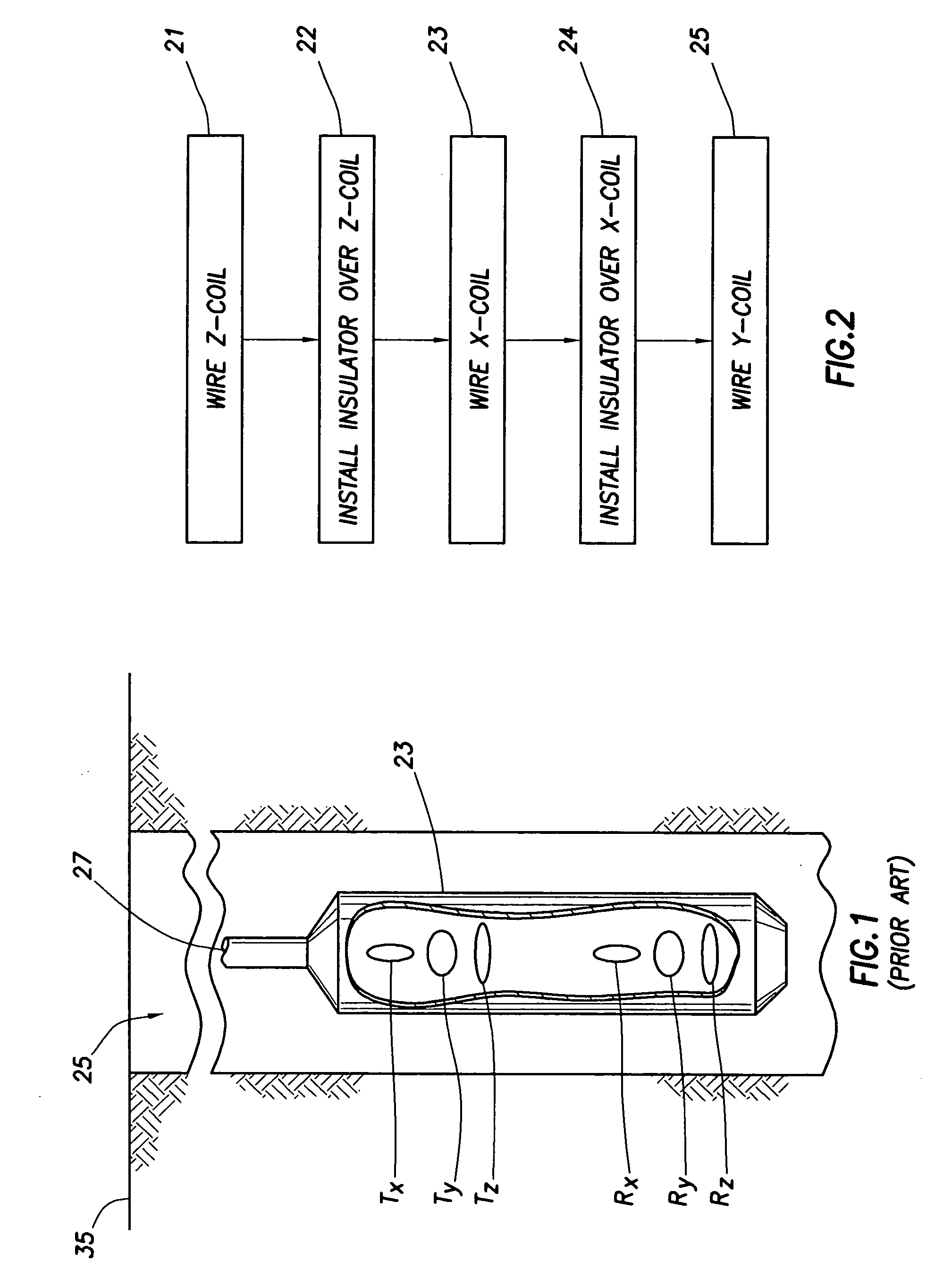
[0030] EM logging tools are well known in the art. FIG. 1 shows a prior art tri-axial EM logging tool (23) lowered into a well (25) by a wireline (27). The EM logging tool (23) includes tri-axial transmitter antennas (Tx, Ty, and Tz) disposed at different locations along the longitudinal axis of the EM logging tool (23). The tri-axial transmitter antennas (Tx, Ty, and Tz) have their magnetic dipoles oriented in orthogonal directions relative to each other. The EM logging tool (23) also includes tri-axial receiver ante...


PUM


Abstract

Techniques for implementing antenna configurations with substantially co-located axes are disclosed. A method for constructing co-located antennas includes winding a first antenna on a support, the first antenna having a first magnetic dipole in a first orientation; and winding a second antenna on the support through a first set of openings in the support, the second antenna having a second magnetic dipole in a second orientation, wherein the first orientation is different from the second orientation, and wherein a center of the first magnetic dipole substantially co-locates with a center of the second magnetic dipole.

Description

CROSS-REFERENCE TO RELATED APPLICATIONS [0001] This application is a divisional application of U.S. patent application Ser. No. 10 / 250,225, filed Jun. 13, 2003, and claims priority to that Application pursuant to 35 U.S.C. § 121. This invention also claims priority pursuant to 35 U.S.C. § 119 of U.S. Provisional Patent Application Ser. No. 60 / 319,433, filed on Jul. 29, 2002. This Provisional Application is hereby incorporated by reference in its entirety.BACKGROUND OF INVENTION [0002] 1. Field of the Invention [0003] The invention relates generally to electromagnetic well logging instruments. More specifically, the invention relates to antennas for electromagnetic well logging instruments. [0004] 2. Background Art [0005] Various well logging techniques are known in the field of oil and gas exploration and production. These techniques typically employ logging tools or “sondes” equipped with sources adapted to emit energy into subsurface formations from a borehole traversing the subsu...

Claims


Application Information

Patent Timeline
Patent Type & Authority Applications(United States)
IPC IPC(8): G01V3/18H01Q1/04
CPCG01V3/30G01V13/00H01Q21/24H01Q7/08H01Q7/00
Inventor CHEN, KUO-CHIANGBARBER, THOMAS D.
Owner SCHLUMBERGER TECH CORP
Why Eureka
Try Eureka