Method and apparatus measuring electrical anisotropy in formations surrounding a wellbore

a technology of electrical anisotropy and measurement method, which is applied in the direction of reradiation, instruments, borehole/well accessories, etc., can solve the problems of inability to measure electrical anisotropy, and inability to accurately measure electrical anisotropy, so as to reduce the effect of borehole and invasion on the measurement, reducing the effect of borehole and invasion

Inactive Publication Date: 2005-10-25
HALLIBURTON ENERGY SERVICES INC
View PDF8 Cites 60 Cited by
  • Summary
  • Abstract
  • Description
  • Claims
  • Application Information

AI Technical Summary

Benefits of technology

[0016]The disclosed methods may provide advantages in determining the parameters of anisotropic earth formations in both wireline applications and / or MWD applications. For example, the tool is expected to work particularly well in high-conductivity formations where the existing induction tools are deficient due to skin effect. Additionally, because the sensitivity to anisotropy is a volumetric effect as opposed to a boundary effect for Galvanic devices, there is a greater sensitivity to anisotropy. In addition due to the fact that the tool operates on straightforward principles, the ease of log interpretation is enhanced. Also, in the case of MWD, the tool design advantageously reduces the borehole and invasion effects on the measurement and enhances the depth of investigation.

Problems solved by technology

Indeed, regarding Galvanic devices, the lack of sensitivity to anisotropy is even more stringent due to the “paradox of anisotropy,” which states that any array of electrodes or sensors deployed along the axis of a wellbore in a vertical well is insensitive to the vertical component of resistivity, despite the intuitive expectation to the contrary.
This instrument may be unduly complex and provide measurements that are difficult to interpret.
Further, the design of this wireline instrument may not be adaptable to a measurement while drilling (MWD) implementation.

Method used


Image

  • Method and apparatus measuring electrical anisotropy in formations surrounding a wellbore
  • Method and apparatus measuring electrical anisotropy in formations surrounding a wellbore
  • Method and apparatus measuring electrical anisotropy in formations surrounding a wellbore

Examples


Embodiment Construction

Terminology

[0026]It is noted that the terms horizontal and vertical as used herein are defined to be those directions parallel to and perpendicular to the bedding plane, respectively.

Tool Configuration

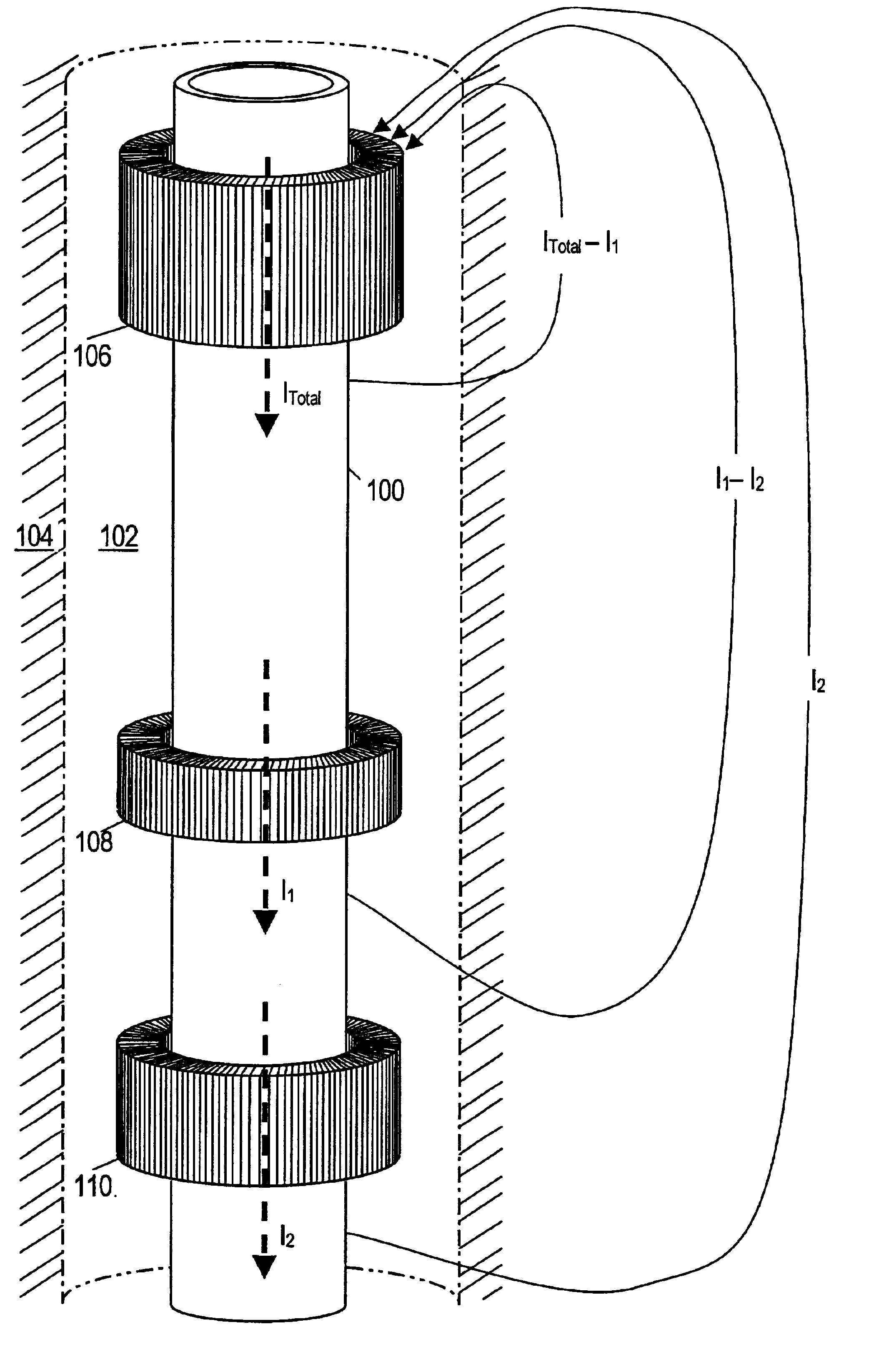
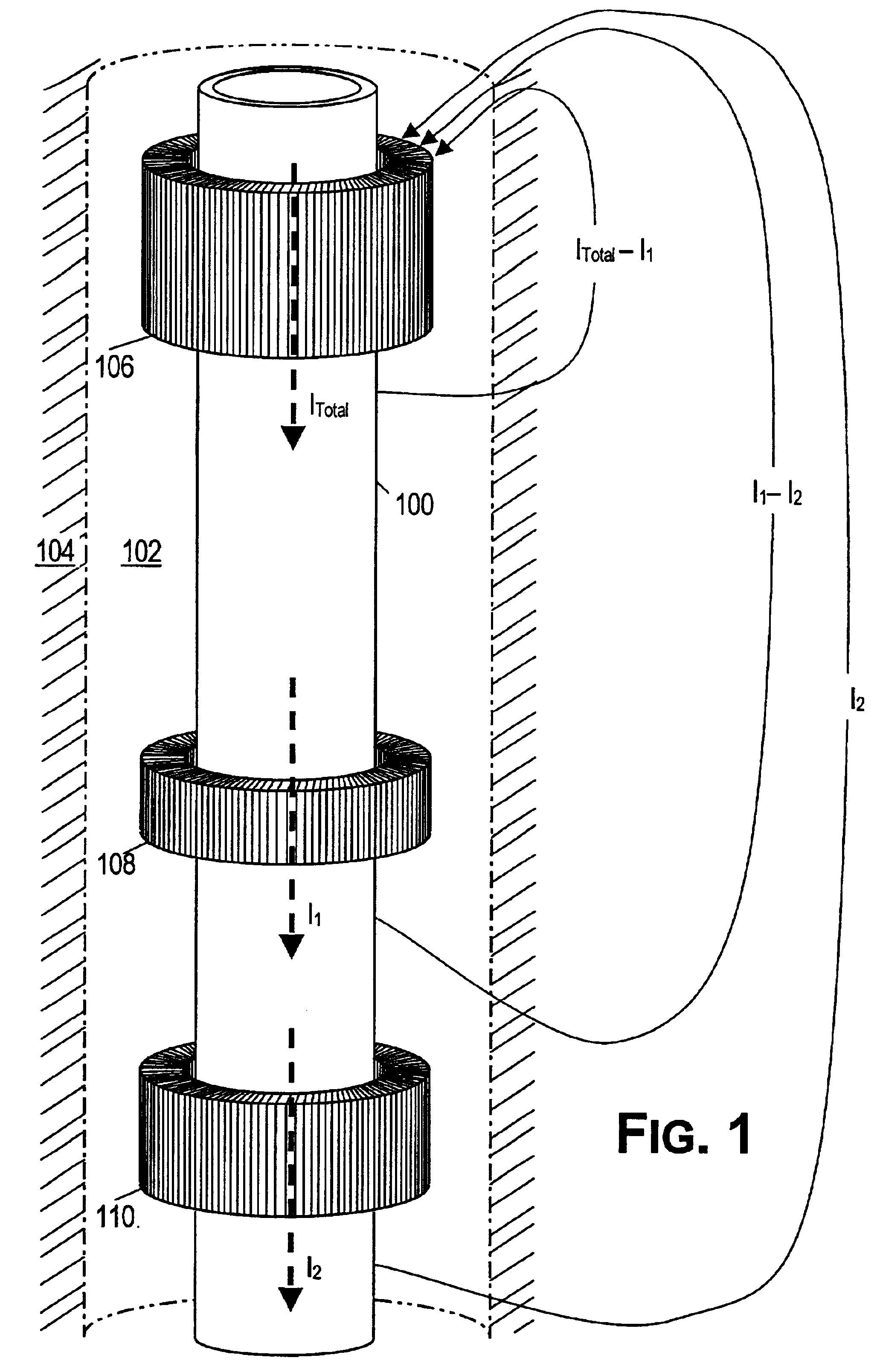
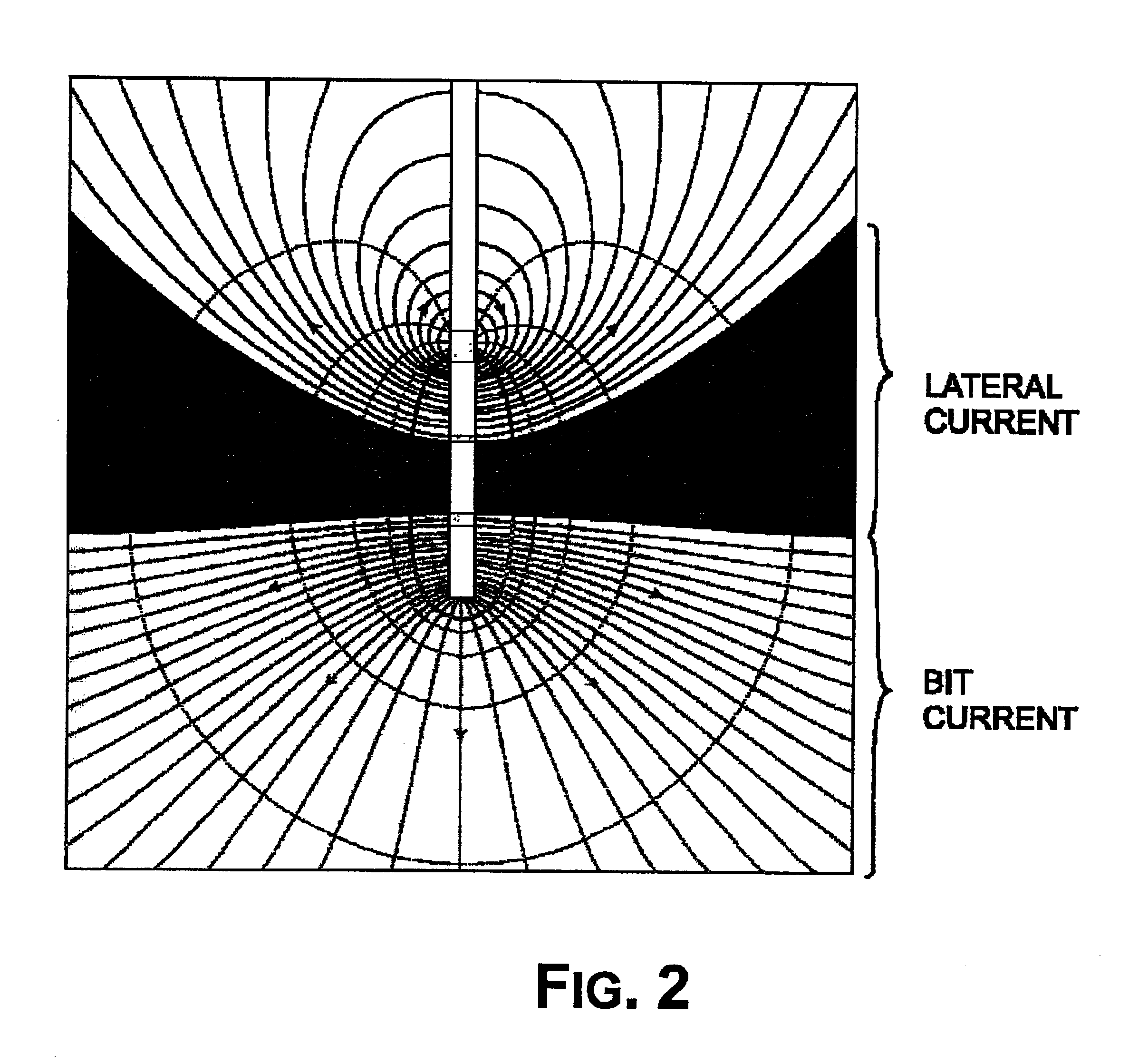
[0027]FIG. 1 shows a logging tool 100 that is part of drillstring located in a wellbore 102 that passes through a formation 104. The tool includes at least one transmitter antenna 106 and at least two receiver antennas 108, 110. The transmitter antenna 106 and receiver antennas 108 and 110 are toroidal antennas, although as explained below the antennas 106, 108, and 110 may include other antenna types. A toroidal antenna has a spirally-wound high-permeability core that forms a closed loop around an electrical conductor. In the logging tool 100, the electrical conductor is preferably a portion of a drill string, but it is not so limited, in fact the logging tool 100 also renders itself to wireline applications. In the preferred embodiment, the core is circular with a generally-rectangul...


PUM


Abstract

A logging tool is disclosed having transmitting and receiving antennas to measure formation anisotropy. The antennas may preferably be combinations of toroidal, horizontal electric dipole, and horizontal magnetic dipole antennas. In one embodiment, the tool: (a) induces a current flow in the tubing or drill string traversing the formation in a borehole; (b) measures a signal difference between two receiver antennas on the drill string; (c) determines an apparent conductivity of the formation from the resistive component of the signal difference; and (d) uses the apparent conductivity to calculate an anisotropy coefficient with a knowledge of the horizontal conductivity. The tool may further determine a second apparent conductivity of the formation from the reactive component of the signal difference, and use both apparent conductivities to calculate the anisotropy coefficient and the horizontal conductivity. The vertical conductivity can also be determined from these two calculated values in the usual manner.

Description

CROSS-REFERENCE TO RELATED APPLICATIONS[0001]This application claims priority to U.S. Provisional Patent Application No. 60 / 302,823 filed on Jul. 3, 2001, and entitled “Method And Apparatus Using Toroidal Antenna for Measuring Electrical Anisotropy.” This application is also related to commonly owned U.S. Pat. No. 6,181,138, issued Jan. 30, 2001, and entitled “Directional Resistivity Measurements for Azimuthal Proximity Detection of Bed Boundaries.” These references are incorporated herein by reference.STATEMENT REGARDING FEDERALLY SPONSORED RESEARCH OR DEVELOPMENT[0002]Not applicable.BACKGROUND OF THE INVENTION[0003]1. Field of the Invention[0004]The present invention generally relates to the measurement of electrical characteristics of formations surrounding a wellbore. More particularly, the present invention relates to a method for determining horizontal and vertical resistivities in anisotropic formations.[0005]2. Description of Related Art[0006]The basic principles and techniq...

Claims


Application Information

Patent Timeline
Patent Type & Authority Patents(United States)
IPC IPC(8): E21B49/00G01V3/28G01V3/18
CPCE21B49/00G01V3/28
Inventor GIANZERO, STANLEY C.
Owner HALLIBURTON ENERGY SERVICES INC
Why Eureka
Try Eureka