

Apparatus and method for coding moving picture
Inactive Publication Date: 2006-03-02
KK TOSHIBA
View PDF4 Cites 46 Cited by
- Summary
- Abstract
- Description
- Claims
- Application Information
AI Technical Summary
Problems solved by technology
However, there is an overhead when a motion vector itself is coded.
Therefore, until the coding process in the peripheral blocks is completed, accurate predicted vectors and weighting factors of motion vector coding costs cannot be determined.
Method used
View moreImage
Smart ImageViewing Examples

Examples
example 1
[0063] A virtual prediction motion vector is calculated with a supposition that all macroblocks are subjected to inter-frame coding.
example 2
[0064] In addition to Example 1, an optimum motion vector in a specific block shape (for example 16×16) in all macroblocks is used to calculate a virtual prediction motion vector.
example 3
[0065] A motion vector of an immediately previous macroblock or a motion vector of an immediately previous block is set as a virtual prediction motion vector.
Login to View More PUM
 Abstract
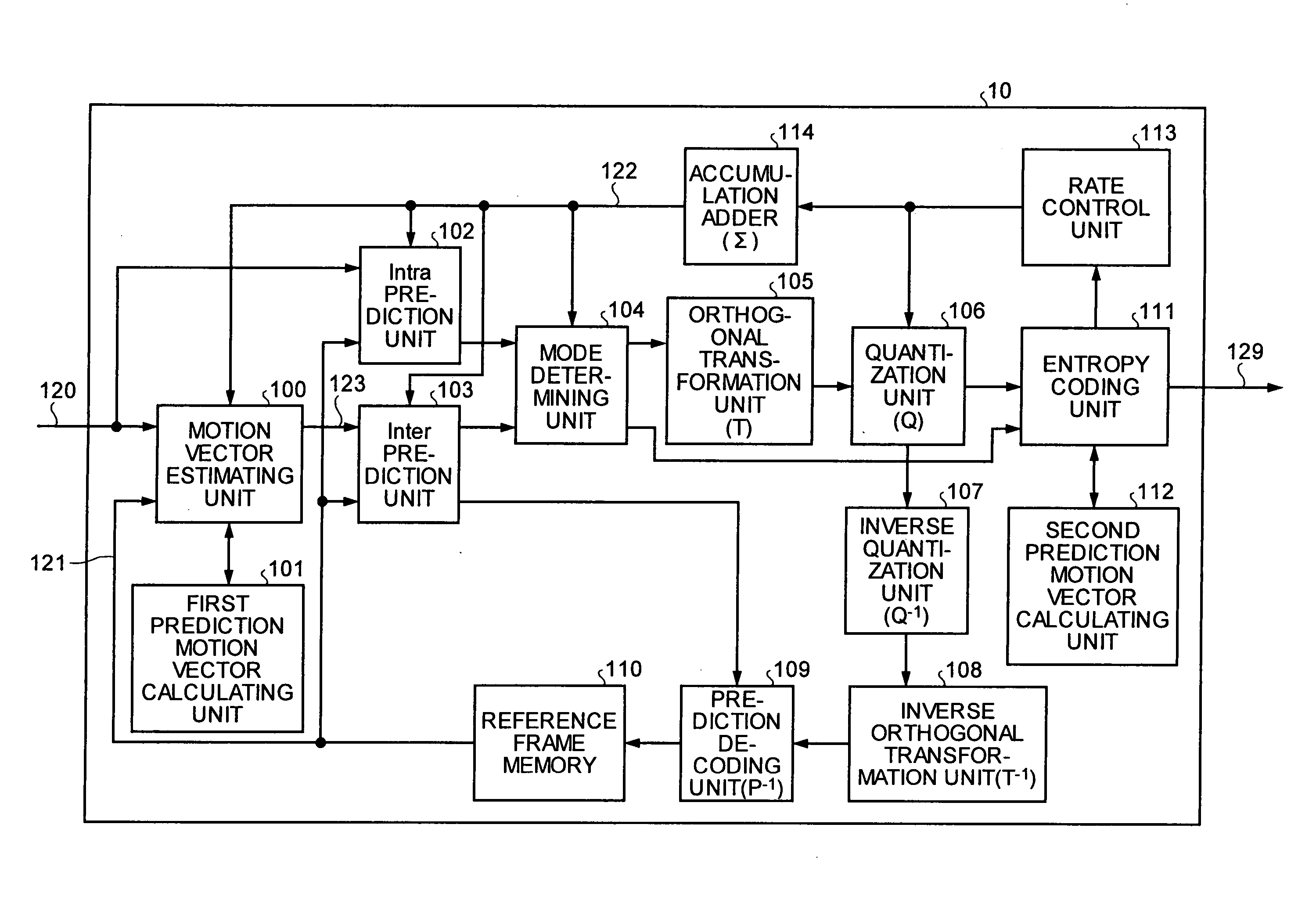
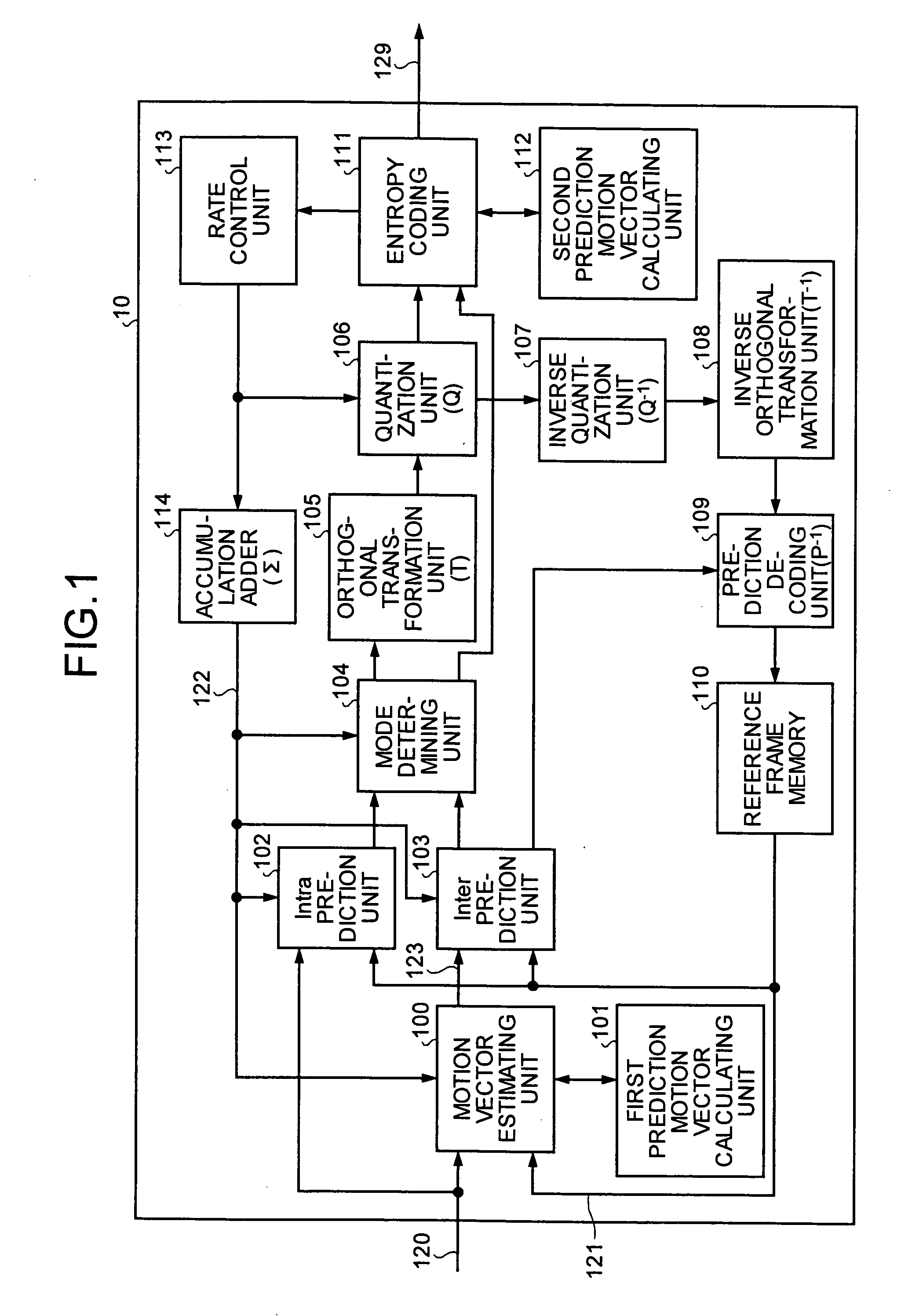
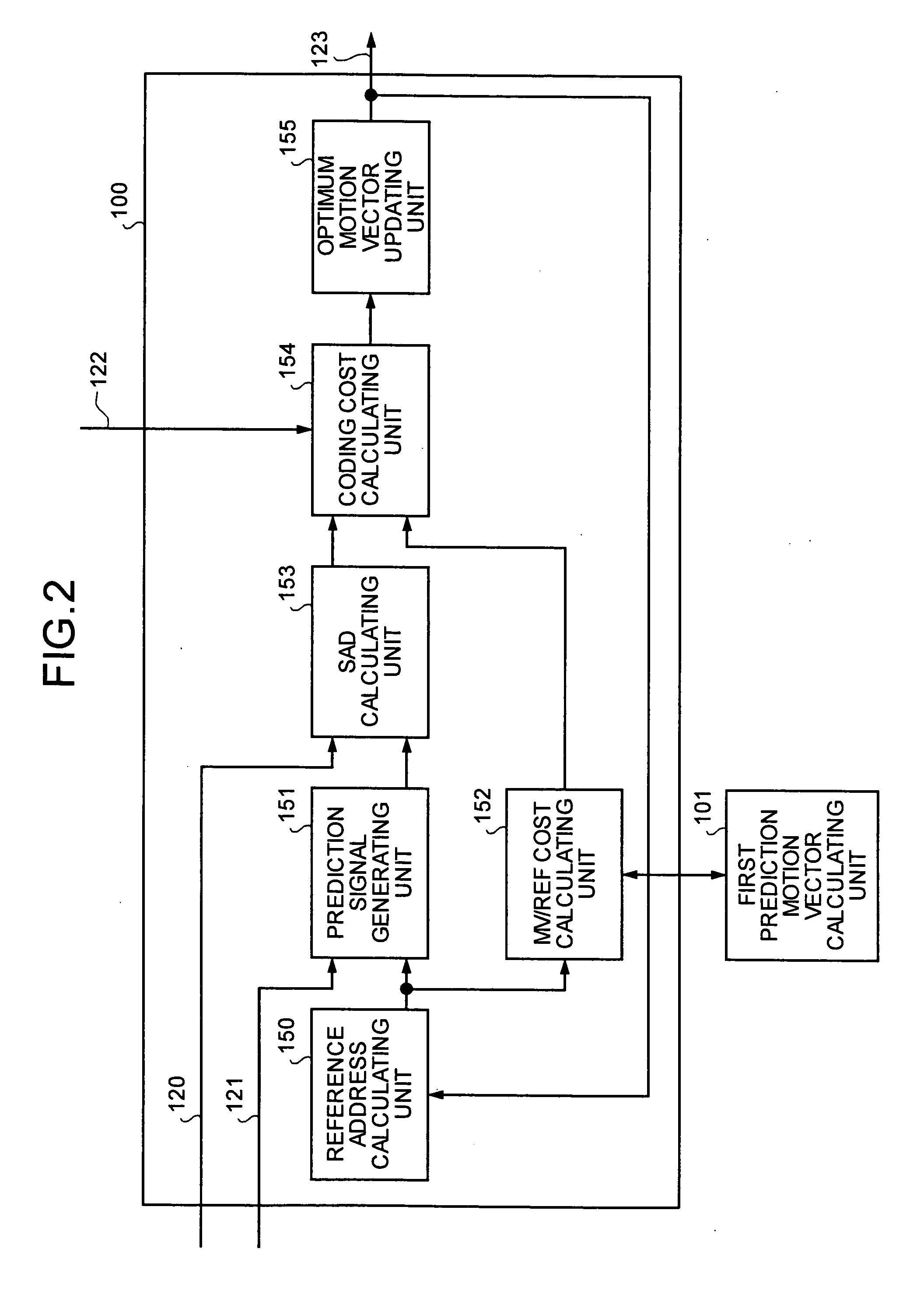
An apparatus for coding a moving picture includes a motion vector generating unit that generates a motion vector based on a first predicted motion vector stored; and a coding information generating unit that generates coding information used to code a target block, based on the motion vector generated by the motion vector generating unit. The apparatus also includes a second predicted motion vector generating unit that generates a second predicted motion vector for the target block; and a coding unit that codes an image of the target block based on the second predicted motion vector.
Description
CROSS-REFERENCE TO RELATED APPLICATIONS [0001] This application is based upon and claims the benefit of priority from the priority Japanese Patent Application No. 2004-255810, filed on Sep. 2, 2004; the entire contents of which are incorporated herein by reference. BACKGROUND OF THE INVENTION [0002] 1. Field of the Invention [0003] The present invention relates to a moving picture coding apparatus, a moving picture coding method, and computer program product, which perform a coding process to a moving picture. [0004] 2. Description of the Related Art [0005] In motion-compensated predictive inter-frame image coding for moving pictures, accuracy of motion vector estimation in coding considerably affects coding efficiency. An amount of process of the motion vector estimation accounts for a large share of the entire coding process. A large number of conventional techniques related to the increases in accuracy and speed of the motion vector estimation are developed (for example, see Algo...
Claims
Login to View More Application Information
Patent Timeline
 IPC IPC(8): H04N11/02H04N7/12H04N11/04H04B1/66H04N19/50H04N19/105H04N19/134H04N19/136H04N19/139H04N19/176H04N19/196H04N19/436H04N19/503H04N19/51H04N19/513H04N19/523H04N19/533H04N19/56H04N19/57H04N19/60H04N19/61H04N19/91
CPCH04N19/56H04N19/139H04N19/176H04N19/61H04N19/567H04N19/109H04N19/124H04N19/152H04N19/11
InventorKOTO, SHINICHIROASANO, WATARU
OwnerKK TOSHIBA