

Molar appliance for an orthodontic brace
- Summary
- Abstract
- Description
- Claims
- Application Information
AI Technical Summary
Benefits of technology
Problems solved by technology
Method used
Image

Examples
Embodiment Construction
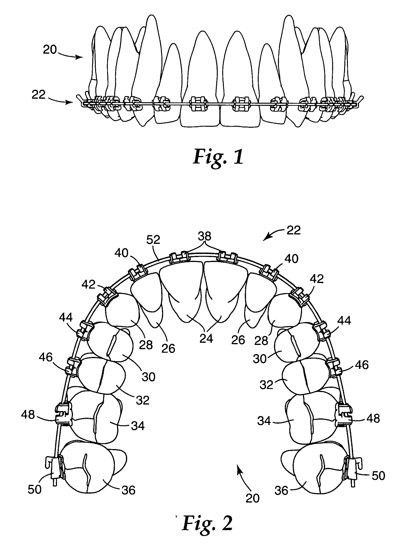
[0031]FIG. 1 illustrates an example of an upper dental arch 20 of an orthodontic patient that is undergoing orthodontic therapy. An orthodontic brace, broadly designated by the numeral 22, is connected to the teeth of the upper dental arch 20. The brace 22 includes a set of appliances along with an archwire that is received in the appliances, as will be described in more detail below.
[0032]FIG. 2 is an enlarged view of the upper dental arch 20 along with the brace 22, looking in an upwardly direction toward the outer or occlusal tips of the teeth. The upper dental arch 22 includes a left quadrant and a right quadrant, each of which has a central incisor tooth 24, a lateral incisor tooth 26, a cuspid tooth 28, a first bicuspid tooth 30, and a second bicuspid tooth 32. In addition, each of the left and right quadrants includes a first molar tooth 34 and a second molar tooth 36.
[0033] The illustration of the upper dental arch 22 shown in FIGS. 1 and 2 is only one example of dentition...
PUM
 Abstract
Description
Claims
Application Information