Cyclonic separating apparatus with tangential offtake conduit

a tangential offtake conduit and separating apparatus technology, applied in the direction of separation processes, vortex flow apparatus, colloidal chemistry, etc., can solve the problems of reversal, loss of kinetic energy of the fluid flow associated with the spinning movement, and failure to achieve pressure recovery wholly successful, so as to reduce the amount of turbulence, improve efficiency and/or performance, and reduce energy loss through friction

Inactive Publication Date: 2002-11-19
DYSON TECH LTD
View PDF10 Cites 62 Cited by
  • Summary
  • Abstract
  • Description
  • Claims
  • Application Information

AI Technical Summary

Benefits of technology

It is an object of the present invention to provide cyclonic separating apparatus in which a greater proportion of the kinetic energy of exiting fluid is recoverable. It is a further object of the present invention to provide cyclonic separating apparatus which, when incorporated into a vacuum cleaner, results in the vacuum cleaner performing with a higher efficiency and / or better performance.
The invention provides a cyclonic separating apparatus comprising a tapering cyclone having an axis, a larger end and a smaller end, a fluid inlet and a fluid outlet located at the larger end of the cyclone, the fluid outlet being located coaxially with the cyclone, and a tangential offtake conduit communication with the fluid outlet, wherein the distance, measured parallel to the axis, between the tangential offtake and the smaller end of the cyclone increases in the downstream direction of the tangential offtake conduit. Preferably, the tangential offtake conduit follows a substantially helical path downstream of the fluid outlet. Such an arrangement allows the fluid exiting the separating apparatus to be gradually turned through a required angle without imposing sharp changes of direction. This reduces the amount of turbelence induced in the fluid flow by virtue of the direction change and this in turn reduces energy loss through friction.
The invention provides cyclonic separating apparatus comprising a tapering cyclone having an axis, a larger end and a smaller end, a fluid inlet and a fluid outlet located at the larger end of the cyclone, the fluid outlet being located coaxially with the cyclone, and a tangential offtake conduit communicating with the fluid outlet, wherein the distance, measured parallel to the axis, between the tangential offtake and the smaller end of the cyclone increases in the downstream direction of the tangential offtake conduit. Preferably, the tangential offtake conduit follows a substantially helical path downstream of the fluid outlet. Such an arrangement allows the fluid exiting the separating apparatus to be gradually turned through a required angle without imposing sharp changes of direction. This reduces the amount of turbulence induced in the fluid flow by virtue of the direction change and this in turn reduces energy loss through friction.
The tangential offtake conduit preferably has a central axis which is inclined at an angle of between 35.degree. and 70.degree., preferably 60.degree., to the longitudinal axis of the cyclone body. This arrangement turns the exiting fluid through a required angle without significantly increasing the possibility of separation occurring as the fluid passes through the tangential offtake conduit. It also allows the kinetic energy of the spinning fluid to be recovered as pressure energy which in turn results in the provision of a highly efficient system for separation of particles from a fluid.
In a preferred embodiment, a centerbody is located in the fluid outlet, which consists of a vortex finder. The tangential offtake conduit then communicates with an annular chamber delimited on the outside by the fluid outlet and on the inside by the centerbody. The arrangement of an annular chamber around the centerbody ensures that all of the exiting air is aligned with the tangential offtake conduit so that the amount of turbulence introduced at the entrance to the tangential offtake conduit is kept to a minimum.

Problems solved by technology

If the offtake conduit leading from the vortex finder is linear with respect to the vortex finder (ie. the conduit has a central axis which is continuous with the central axis of the vortex finder), then the outgoing fluid will continue to spin as it travels along the conduit but will, eventually, revert to linear flow and the kinetic energy of the fluid flow associated with the spinning movement will be lost, probably in the form of frictional losses.
However, the pressure recovery is not wholly successful.
This results in turbulent flow downstream of the vortex finder which leads to energy loss from the fluid.

Method used


Image

  • Cyclonic separating apparatus with tangential offtake conduit
  • Cyclonic separating apparatus with tangential offtake conduit
  • Cyclonic separating apparatus with tangential offtake conduit

Examples


Embodiment Construction

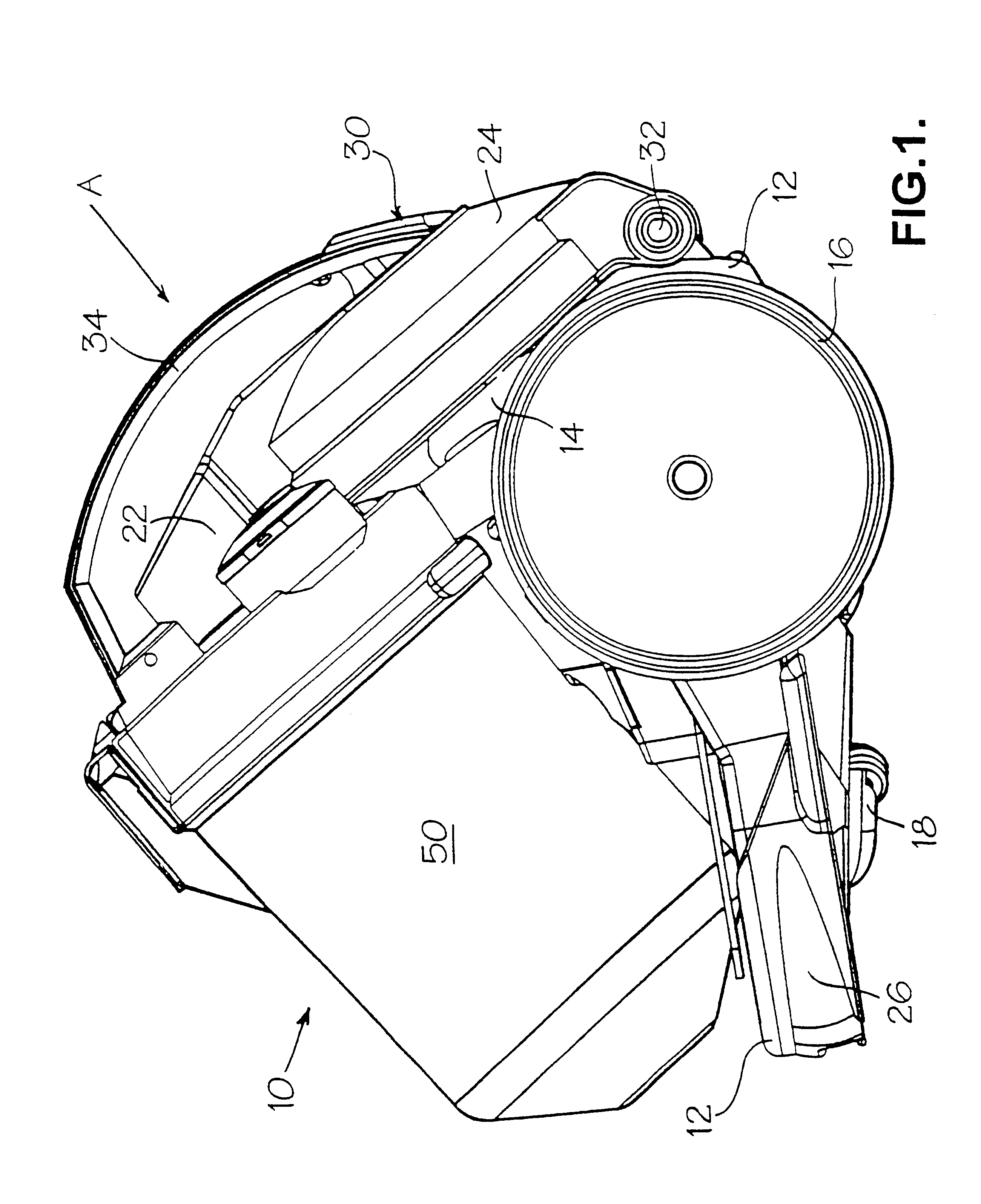
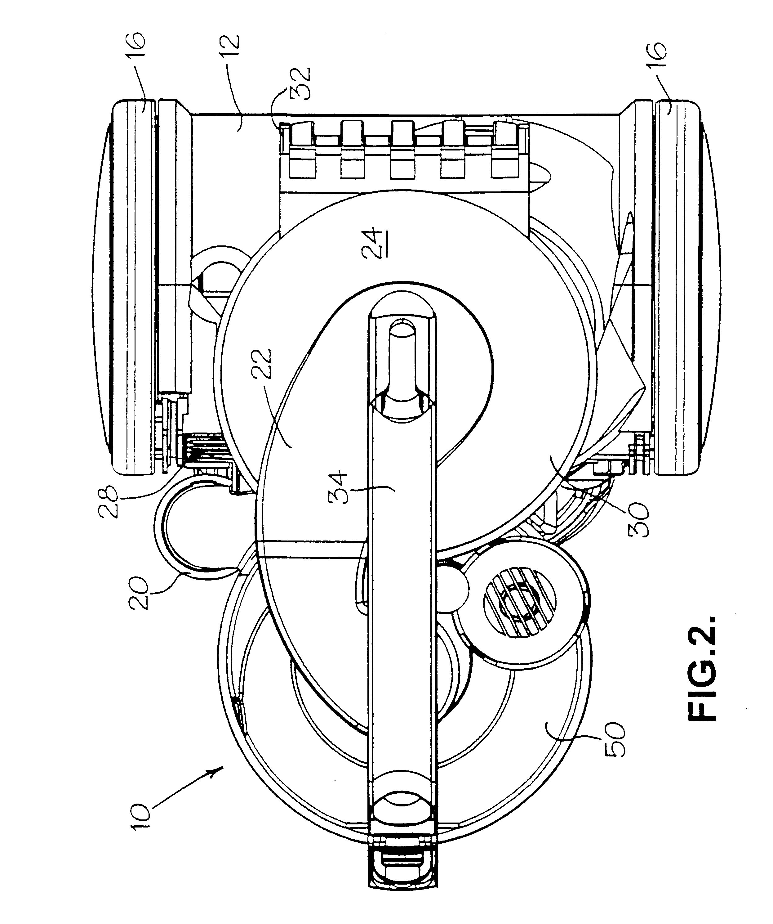
Cyclonic separating apparatus according to the invention can be incorporated to good effect in a vacuum cleaner. A vacuum cleaner incorporating cyclonic separating apparatus according to the invention is shown in FIGS. 1 and 2. The vacuum cleaner 10 has a chassis 12 which supports a motor and fan unit 14 and cyclonic separating apparatus 50. Support wheels 16 are mounted on the chassis 12 towards the rear thereof and a castor wheel 18 is arranged beneath the chassis 12 towards the front thereof to allow the cleaner 10 to be maneouvred across a surface to be cleaned The motor and fan unit 14 is arranged substantially between the support wheels 16 to give the cleaner 10 a high degree of maneouvrability.

The cyclonic separating apparatus 50 is designed to effect the separation of dirt and dust particles from an airflow which is drawn into the cleaner 10 by the motor and fan unit 14. A hose (not shown) carrying a floor tool is connected to an air inlet 20 of the cyclonic separating appar...


PUM

PropertyMeasurementUnit
angleaaaaaaaaaa
angleaaaaaaaaaa
angleaaaaaaaaaa

Abstract

The invention provides cyclonic separating apparatus comprising a tapering cyclone having a larger end a smaller end, a fluid outlet located at the larger end of the cyclone, the fluid outlet becoming located coaxially with the cyclone, and a tangential offtake conduit communicating with the fluid outlet, wherein the distance between the tangential offtake conduit and the smaller end of the cyclone increases in the downstream direction of the tangential offtake conduit. Preferably, the tengential offtake conduit follows a substantially helical path. This reduces the turbulence created in the tangential offtake conduit and allows kinetic energy of the exiting fluid to be recovered as pressure energy.

Description

TECHNICAL FIELD OF THE INVENTIONThe invention relates to cyclonic separating apparatus. Particularly, but not exclusively, the invention relates to cyclonic separating apparatus for use in vacuum cleaners.BACKGROUND OF THE INVENTIONCyclonic separating apparatus in which particulate material is separated from a fluid, usually a gas, by means of high centrifugal forces is known. Such apparatus comprises a tapering cyclone body having a fluid inlet located at the larger end of the cyclone body and arranged to introduce fluid to the interior surface of the cyclone body in a tangential manner. The smaller end of the cyclone body is surrounded by a collector or, alternatively, leads to a particulate material outlet. A fluid outlet in the form of a vortex finder is located centrally of the larger end of the cyclone body. In use, the fluid inlet introduces the fluid with the particulate material entrained therein to the interior of the cyclone body in a tangential manner. The taper of the c...

Claims


Application Information

Patent Timeline
Patent Type & Authority Patents(United States)
IPC IPC(8): A47L9/10A47L9/16B01D45/12B04C9/00B04C5/187B04C5/12B04C5/13B04C5/00B04C5/081B04C5/04
CPCY10S55/03A47L9/1633A47L9/1666A47L5/36A47L9/12B04C5/12B04C5/13
Inventor DYSON, JAMESJUPP, SIMEON CHARLESMACLEOD, ANDREW
Owner DYSON TECH LTD
Why Eureka
Try Eureka