
Wireless communication system, relay station device and base station device

a relay station and wireless communication technology, applied in line-transmission, repeater circuits, line-transmission details, etc., can solve problems such as expansion of service, inability to communicate with bs, and dead zones

Inactive Publication Date: 2006-03-02
KDDI CORP
View PDF4 Cites 314 Cited by
  • Summary
  • Abstract
  • Description
  • Claims
  • Application Information

AI Technical Summary

Benefits of technology

The present invention provides a wireless communication system that includes a base station device, a relay station device, and wireless terminal devices. The base station device transmits scheduling information and a burst packet to the relay station device and the wireless terminal devices, which in turn generate notification information to control synchronization of reception by the wireless terminal device. The relay station device transmits the scheduling information and notification information to the wireless terminal devices, along with the burst packet. The base station device also fixes the transmission position of the scheduling information in wireless frames. The technical effects of the invention include improved synchronization and reduced latency in wireless communication.

Problems solved by technology

In general wireless communication, due to such effects as shadowing arising from blockage by buildings and other obstructions between transmission / reception antennas, there exist dead zones in which communication with the BS is not possible, despite being within the service area.
This is a serious problem for areal expansion of service.

Method used


Image

  • Wireless communication system, relay station device and base station device
  • Wireless communication system, relay station device and base station device
  • Wireless communication system, relay station device and base station device

Examples


first embodiment

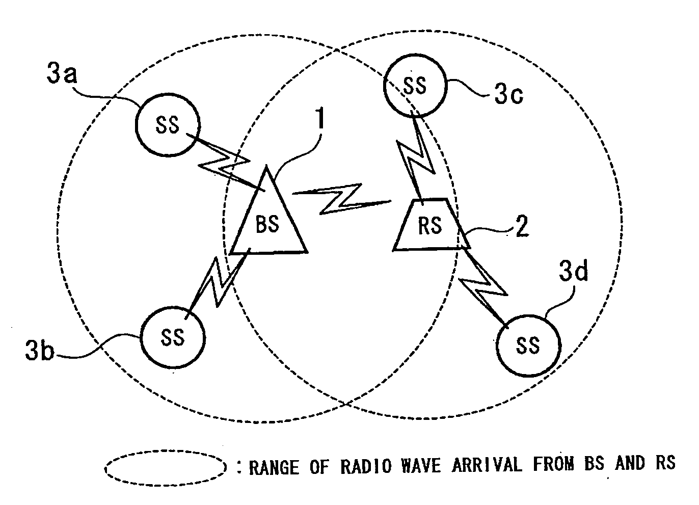
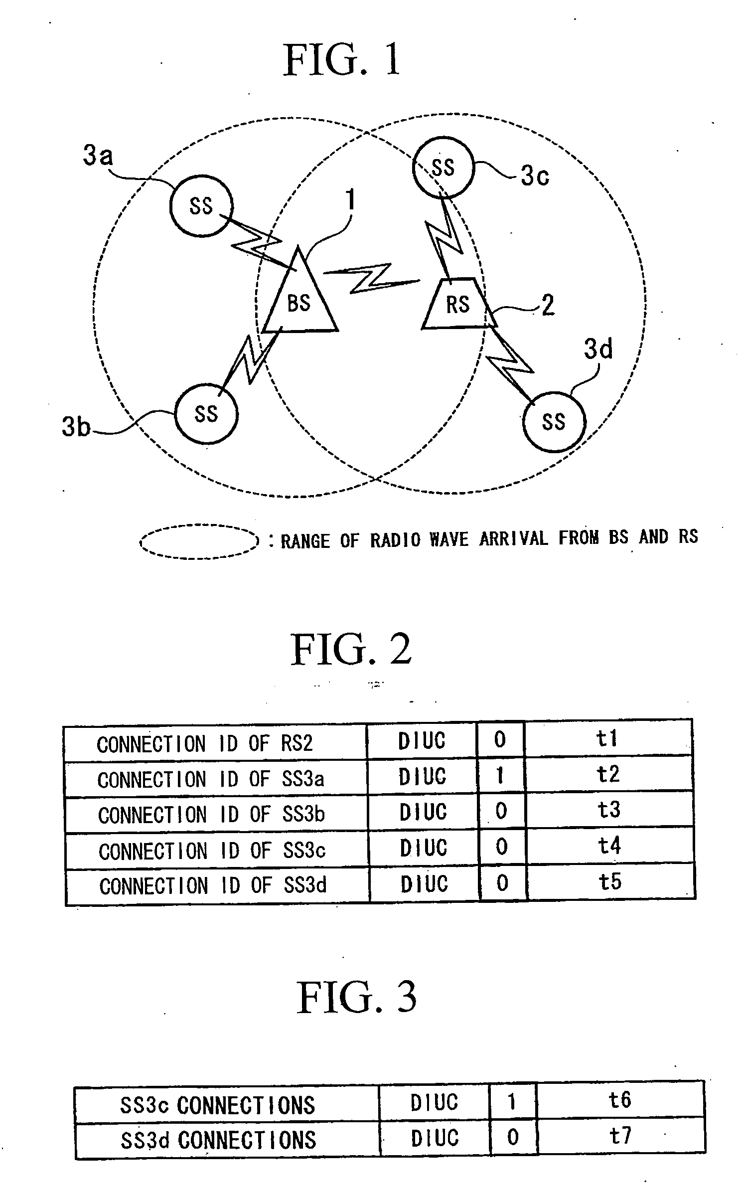
[0041] the invention will be explained below, taking into account the above problems. FIG. 1 shows in summary the configuration of a wireless network of this embodiment. In the drawing, BS 1 is a base station device, and RS 2 is a relay station device which relays information. The BS 1 and RS 2 are fixed installations, however, whereas the BS 1 cannot easily be moved due to circumstances of the installation, the RS 2 can be made smaller in size than the BS 1, and the site of installation can be moved. SS 3a to SS 3d are portable telephone terminals, PDAs (Personal Digital Assistants), fixed-type or portable-type PCs (Personal Computers), or other wireless terminal devices. SS 3a and SS 3b are directly connected to the BS 1; SS 3c and SS 3d are connected to the BS 1 via the RS 2.

[0042] The BS 1 obtains an antenna to transmit and receive radio signals, a transmission / reception portion to perform modulation, demodulation, and other processing of signals being transmitted and received, ...

second embodiment

[0059] Next, the invention will be explained. In this embodiment, the BS 1 transmits a DL burst packet in succession to a MAP message. This embodiment alone can be implemented only when FDD is used as the duplex method. FIG. 8 shows the configuration of a wireless frame in this embodiment. Similarly to a conventional device, the BS 1 transmits the remaining DL burst packets in succession to a DL burst packet including a long preamble, FCH, and MAP message.

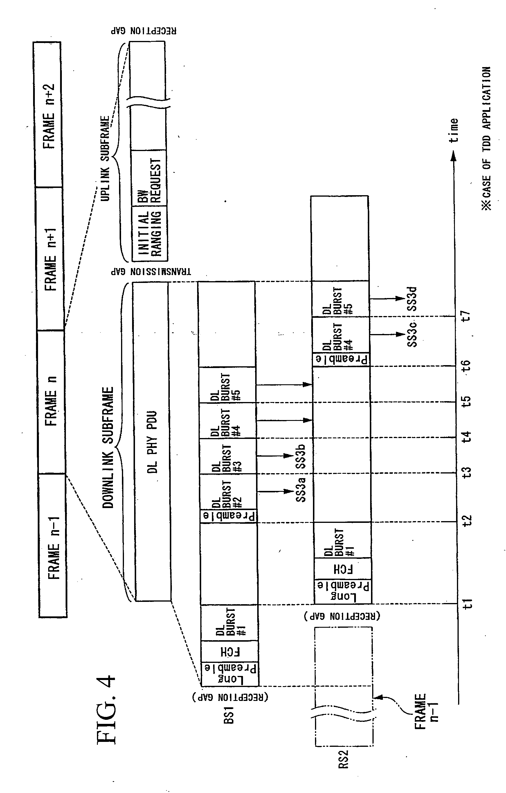
[0060] In this case, as shown in FIG. 8, the MAP message transmitted from the RS 2 is always fixed at the final portion of the frame. Also, in a MAP message transmitted from the RS 2, only the scheduling for the next frame and beyond is specified. That is, the Preamble Present bit is set to 1 in the DL-MAP IE corresponding to the first burst of DL burst packets continuing after the next frame. In FIG. 8, a DL burst packet transmitted from the RS 2 to the SS 3c and SS 3d is not the DL burst packet which is received immediately befor...

third embodiment

[0063] Next, the invention will be explained. In this embodiment, there is no need to fix the sizes of either of the first DL burst packets transmitted by the BS 1 and RS 2. That is, the sizes of the DL-MAP IE and UL-MAP IE transmitted by the RS 2 can be specified dynamically.

[0064] In this case, as shown in FIG. 9, the transmission position of MAP messages transmitted from the RS 2 is always set in advance to a prescribed position in wireless frames as seen from the BS 1. The BS 1 performs transmission of DL burst packets so as not to overlap with the timing of MAP messages transmitted by the RS 2. Consequently when the timing of a MAP message transmitted by the RS 2 arrives before completion of transmission of DL burst packets by the BS 1, after the RS 2 transmits the MAP message, the BS 1 restarts transmission of DL burst packets from the DL burst packet with the preamble.

[0065] That is, the BS 1 discriminates the DL burst packets transmitted before arrival of the MAP message tr...


PUM


Abstract

A wireless communication system, relay station device, and base station device reduce dead zones in which communication with the base station device is not possible, and enable expansion of service areas. The BS transmits to the RS burst packets and MAP messages including information providing notification of the timing of information transmission and reception. The RS receives the MAP messages and burst packets. The RS stores, in the Preamble Present bits in MAP messages, information providing notification of the preamble transmission timing to control synchronization of reception by the SSs, and transmits the MAP messages to the SSs. The RS transmits burst packets to which preambles are appended to the SSs.

Description

BACKGROUND OF THE INVENTION [0001] 1. Field of the Invention [0002] This invention relates to an IEEE 802.16 system or other wireless communication system obtaining a base station device and a relay station device which relays information, and which also obtains a wireless terminal device which performs wireless communication with the base station device via the relay station device, in which wireless frames are repeated with a fixed period. This invention also relates to the relay station device and base station device used in the wireless communication system. [0003] Priority is claimed on Japanese Patent Application No. 2004-253950, filed Sep. 1, 2004, the content of which is incorporated herein by reference. [0004] 2. Description of the Related Art [0005] In the IEEE 802.16 standard for high-speed wireless data communication (hereafter called “the 802.16 standard”), P-MP (point to multipoint) and mesh network architectures are defined for communication. In a P-MP architecture, a...

Claims


Application Information

Patent Timeline
Patent Type & Authority Applications(United States)
IPC IPC(8): H04B3/36
CPCH04B7/155H04W88/085H04B7/2606
Inventor IZUMIKAWA, HARUKIFUKUHARA, TADAYUKI
Owner KDDI CORP
Learn More