Electroactive polymer-based actuation mechanism for grasper

Active Publication Date: 2006-03-02
CILAG GMBH INT
View PDF99 Cites 554 Cited by
  • Summary
  • Abstract
  • Description
  • Claims
  • Application Information

AI Technical Summary

Benefits of technology

[0010] While various techniques can be used to move the articulation joint using the end effector, in one embodiment the elongate shaft can include a slide bar extending therethrough and having a distal end coupled to the articulation joint. The electroactive polymer actuator can be configured to move the slide bar laterally to effect movement of the end effector. For example, the electroactive polymer actuator can include first and second electroactive polymer actuators disposed on opposed sides of the slide bar. The slide bar can include gears formed on a distal end thereof and adapted to engage corresponding gears formed in the articulation joint. In another embodiment, the articulation joint can be in the form of a pivot joint, and the electroactive polymer actuator can include a first electroactive polymer actuator extending between a first side of the end effector and a first side of the elongate shaft, and a second electroactive polymer actuator extending between a second opposed side of the end effector and a second opposed side of the elongate shaft. In yet another embodiment, the articulation joint can be in the form of a flexible portion formed between the elongate shaft and the end effector. The electroactive polymer actuator can include a plurality of electroactive polymer actuators coupled to the flexible portion at distinct locations, each of the plurality of electroactive polymer actuators being configured to change orientations when energy is selectively delivered thereto to flex the flexible portion.
[0011] Methods for grasping tissue are also provided and in one exemplary embodiment the method can include inserting an elongate shaft of a grasping device into a body lumen to position opposed jaws of an end effector movably coupled to a distal end of th...

Problems solved by technology

One drawback to such articulating devices, however, is that a mechanical linkage is used to transfer a force from a handle of the device to the end effec...

Method used


Image

  • Electroactive polymer-based actuation mechanism for grasper
  • Electroactive polymer-based actuation mechanism for grasper
  • Electroactive polymer-based actuation mechanism for grasper

Examples


Embodiment Construction

[0035] Certain exemplary embodiments will now be described to provide an overall understanding of the principles of the structure, function, manufacture, and use of the devices and methods disclosed herein. One or more examples of these embodiments are illustrated in the accompanying drawings. Those of ordinary skill in the art will understand that the devices and methods specifically described herein and illustrated in the accompanying drawings are non-limiting exemplary embodiments and that the scope of the present invention is defined solely by the claims. The features illustrated or described in connection with one exemplary embodiment may be combined with the features of other embodiments. Such modifications and variations are intended to be included within the scope of the present invention.

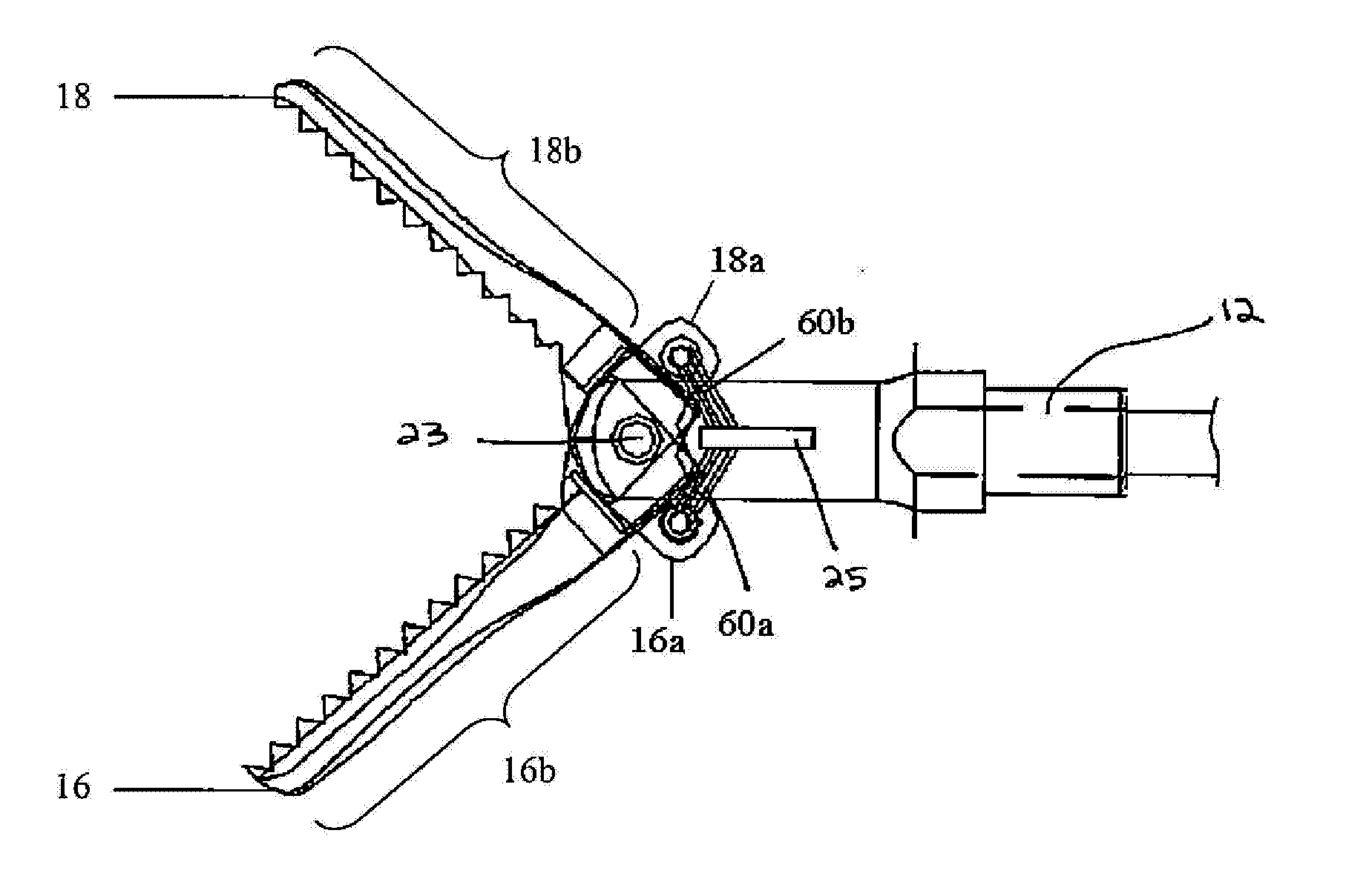
[0036] The present invention generally provides methods and devices for effecting movement of one or more components of a grasping device. In one exemplary embodiment, the grasping device ...


PUM

PropertyMeasurementUnit
Energyaaaaaaaaaa

Abstract

Methods and devices are provided for actuating and/or articulating a grasping device. In one exemplary embodiment, a grasping device is provided having a shaft with an end effector having opposed jaws coupled to the shaft. An electrically expandable and contractible actuator, such as an electroactive polymer actuator, can be used to actuate the end effector to open and close the opposed jaws to grasp tissue or other objects. In another embodiment, an electroactive polymer actuator can be used to pivotally or angularly adjust a position of the end effector relative to the shaft by delivering energy to the electroactive polymer actuator.

Description

CROSS REFERENCE TO RELATED APPLICATIONS [0001] This application is a continuation-in-part of U.S. patent application Ser. No. 11 / 082,495 filed on Mar. 17, 2005 and entitled “Surgical Instrument Incorporating an Electrically Actuated Articulation Mechanism,” which claims priority to U.S. Provisional Application No. 60 / 591,694 filed on Jul. 28, 2004 and entitled “Surgical Instrument Incorporating an Electrically Actuated Articulation Mechanism.” These applications are hereby incorporated by reference in their entireties.FIELD OF THE INVENTION [0002] The present invention relates broadly to surgical devices, and in particular to methods and devices for articulating and / or actuating a grasping device. BACKGROUND OF THE INVENTION [0003] Endoscopic surgical instruments are often preferred over traditional open surgical devices since a smaller incision tends to reduce the post-operative recovery time and complications. Consequently, significant development has gone into a range of endoscop...

Claims


Application Information

Patent Timeline
IPC IPC(8): A61B17/28
CPCA61B17/07207A61B17/29A61B2017/00017A61B2017/00398A61B2017/00871A61B2017/2927A61B2017/2946
Inventor ORTIZ, MARKSHELTON, FREDERICKSWAYZE, JEFFREY
Owner CILAG GMBH INT
Why Eureka
Try Eureka