Wafer level optical system

a technology of optical system and optical lens, applied in the field of optical lens system, can solve the problems of high power consumption, long response time, and limited accuracy

Inactive Publication Date: 2012-03-29
BAYER MATERIALSCIENCE AG
View PDF5 Cites 53 Cited by
  • Summary
  • Abstract
  • Description
  • Claims
  • Application Information

AI Technical Summary

Benefits of technology

[0010]The one or more EAP actuators include one or more EAP transducers and one or more output members are integrated with one or more of a lens portion, a sensor portion and a shutter / aperture portion of the subject lens systems / devices. The lens portion (i.e., the lens stack or barrel) includes at least one lens. In certain embodiments, the lens portion typically includes a focusing lens component as well as an afocal lens component. The sensor portion includes an image sensor which receives the image from the lens portion of the device for digital processing by image processing electronics. Activation of the EAP actuators(s), i.e., by the application of a voltage to the EAP transducer, adjusts the relative position of a lens and / or sensor component to effect or modify an optical parameter of the lens system.

Problems solved by technology

There are many disadvantages to such conventional systems—power consumption is high, response times are long, accuracy is limited and space requirements are high.
While the majority of such camera phones employ an all-mechanical lens module having a small form factor lens, this approach does not offer variable or auto-focusing, zoom and image stabilization capabilities due to the significant number of moving parts required.
However, a downside to lighter and smaller cameras, particularly those with capabilities for longer exposure times and having higher resolution sensors, is the greater effect that camera shake, due primarily to hand jitter, has on the quality of photographs, i.e., causing blurring.
A gyroscope measures pitch and yaw, however, it is not capable of measuring roll, i.e., rotation about the axis defined by the lens barrel.
Further, due to the necessity of an extensive number of moving components, power consumption is significantly high and manufacturing costs are increased.

Method used


Image

  • Wafer level optical system
  • Wafer level optical system
  • Wafer level optical system

Examples


Embodiment Construction

[0053]Before the devices, systems and methods of the present invention are described, it is to be understood that this invention is not limited to a particular form fit or applications as such may vary. Thus, while the present invention is primarily described in the context of a variable focus camera lens, the subject optical systems may be used in microscopes, binoculars, telescopes, camcorders, projectors, eyeglasses as well as other types of optical applications. It is also to be understood that the terminology used herein is for the purpose of describing particular embodiments only, and is not intended to be limiting, since the scope of the present invention will be limited only by the appended claims.

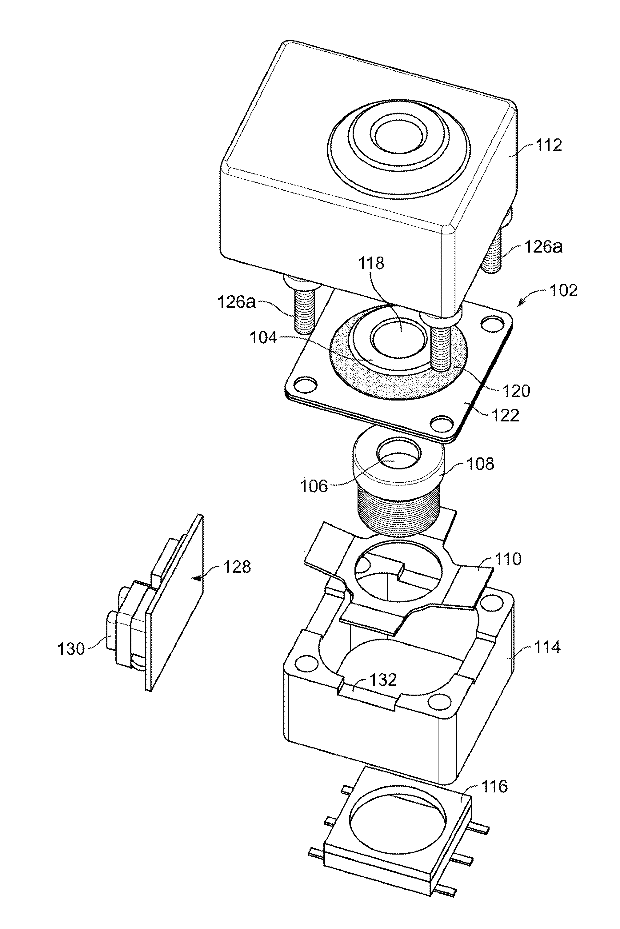
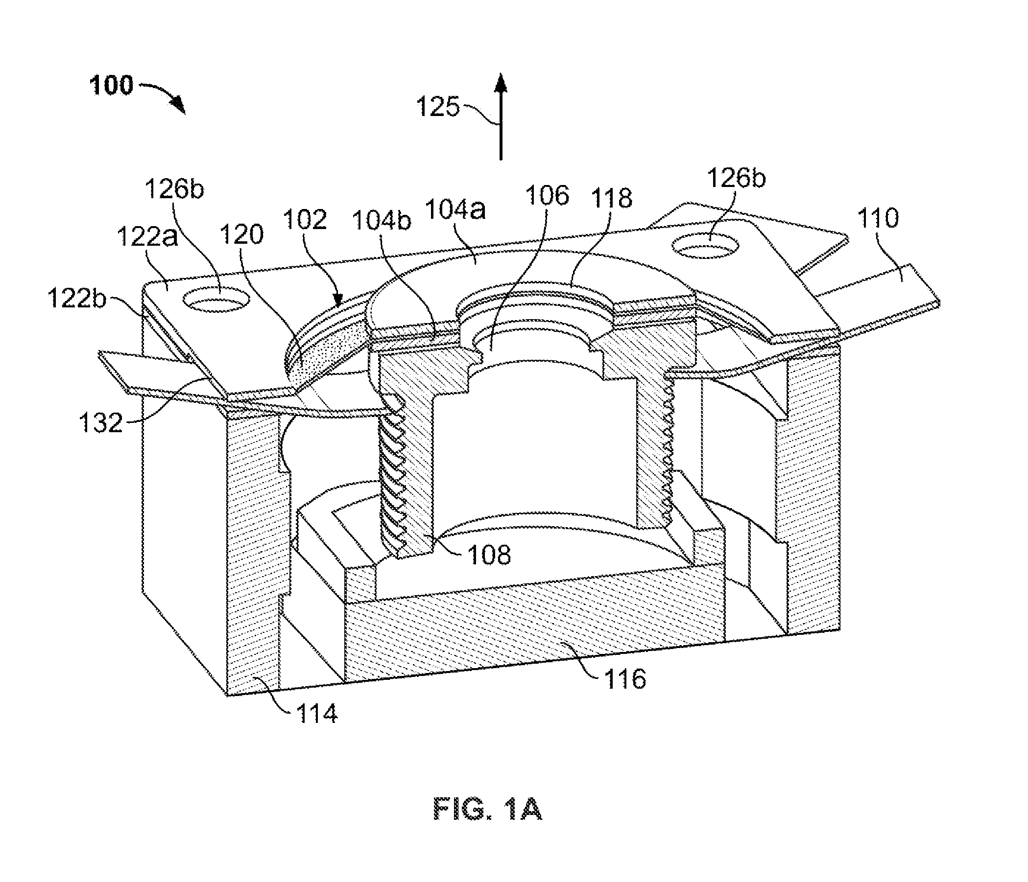
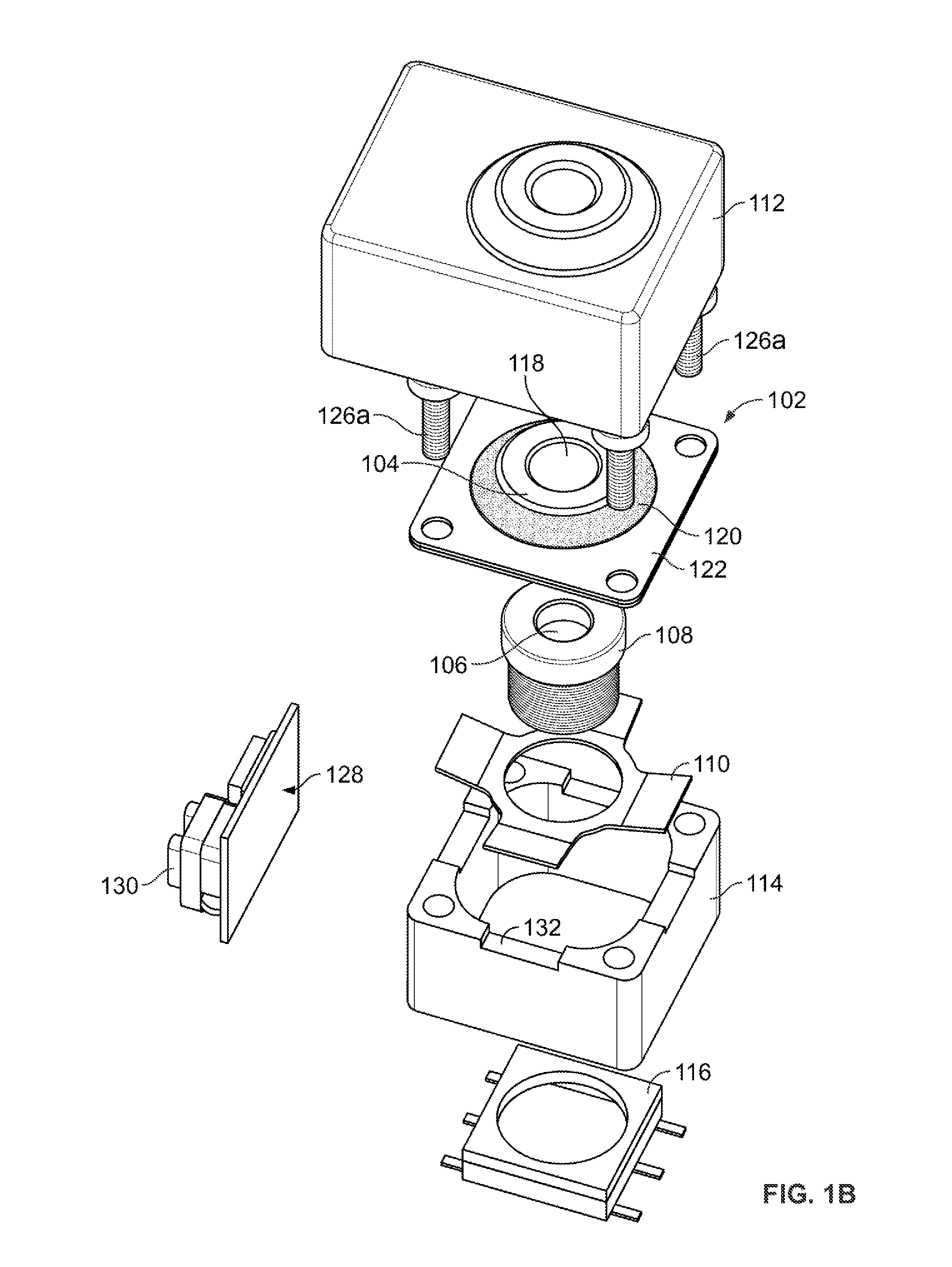
[0054]Referring now to the drawings, FIGS. 1A and 1B illustrate an optical lens system of the present invention having auto-focus capabilities. The figures detail a lens module 100 having a lens barrel 108 holding one or more lenses (not shown). An aperture 106 is provided at a dis...


PUM


Abstract

The present invention provides optical systems, devices and methods which utilize one or more electroactive polymer actuators to adjust an optical parameter of the optical device or system.

Description

RELATED APPLICATION[0001]The present application is a non-provisional of U.S. Provisional Application No. 61 / 161,374 filed Mar. 18, 2009, the content of which is incorporated herein by reference in its entirety.FIELD OF THE INVENTION[0002]The present invention relates to optical lens systems and, in particular, relates to such systems employing electroactive polymer transducers to adjust the lens to provide auto-focusing, zoom, image stabilization and / or shutter / aperture capabilities.BACKGROUND[0003]In conventional optical systems, such as in digital cameras, motors and solenoids are used as sources of power to displace gears and cams which act upon optical elements, e.g., lenses, to provide focusing, zoom, and image stabilization (also referred to as shake prevention). There are many disadvantages to such conventional systems—power consumption is high, response times are long, accuracy is limited and space requirements are high.[0004]Advancements in miniaturized technologies have l...

Claims


Application Information

Patent Timeline
Patent Type & Authority Applications(United States)
IPC IPC(8): H04N5/225
CPCG02B7/102G02B13/004G02B13/0075G02B27/646G03B3/10G03B2205/0046G03B2205/0007H04N5/2254H04N5/2257H04N5/23248H04N5/23287G03B5/00H04N23/57H04N23/55H04N23/60H04N23/68H04N23/687H04N23/00
Inventor BLASCH, IAN
Owner BAYER MATERIALSCIENCE AG
Why Eureka
Try Eureka