Optical lens image stabilization systems

a technology of image stabilization and optical lens, applied in the field of optical lens systems, can solve the problems of high power consumption, long response time, and limited accuracy

Active Publication Date: 2009-02-12
BAYER MATERIALSCIENCE AG
View PDF4 Cites 65 Cited by
  • Summary
  • Abstract
  • Description
  • Claims
  • Application Information

AI Technical Summary

Benefits of technology

[0008]The one or more EAP actuators include one or more EAP transducers and one or more output members are integrated with one or more of a lens portion, a sensor portion and a shutter/aperture portion of the subject lens systems/devices. The lens portion (i.e., the lens stack or barrel) includes at least one lens. In certain embodiments, the lens portion typically includes a focusing lens component as well

Problems solved by technology

There are many disadvantages to such conventional systems—power consumption is high, response times are long, accuracy is limited and space requirements are high.
While the majority of such camera phones employ an all-mechanical lens module having a small form factor lens, this approach does not offer variable or auto-focusing, zoom and image stabilization capabilities due to the significant number of moving parts required.
However, a downside to lighter and smaller cameras, particularly those wit

Method used


Image

  • Optical lens image stabilization systems
  • Optical lens image stabilization systems
  • Optical lens image stabilization systems

Examples


Embodiment Construction

[0057]Before the devices, systems and methods of the present invention are described, it is to be understood that this invention is not limited to a particular form fit or applications as such may vary. Thus, while the present invention is primarily described in the context of a variable focus camera lens, the subject optical systems may be used in microscopes, binoculars, telescopes, camcorders, projectors, eyeglasses as well as other types of optical applications. It is also to be understood that the terminology used herein is for the purpose of describing particular embodiments only, and is not intended to be limiting, since the scope of the present invention will be limited only by the appended claims.

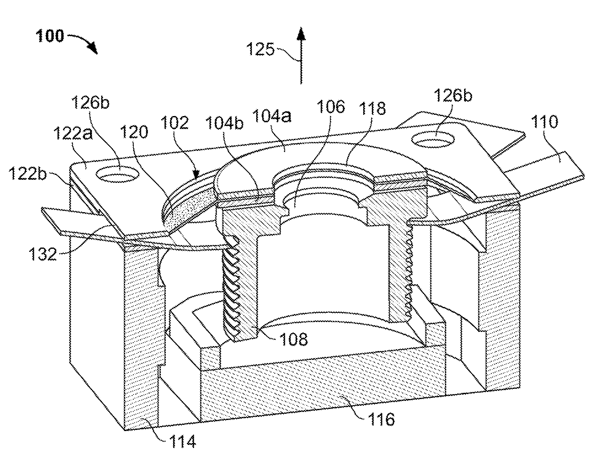
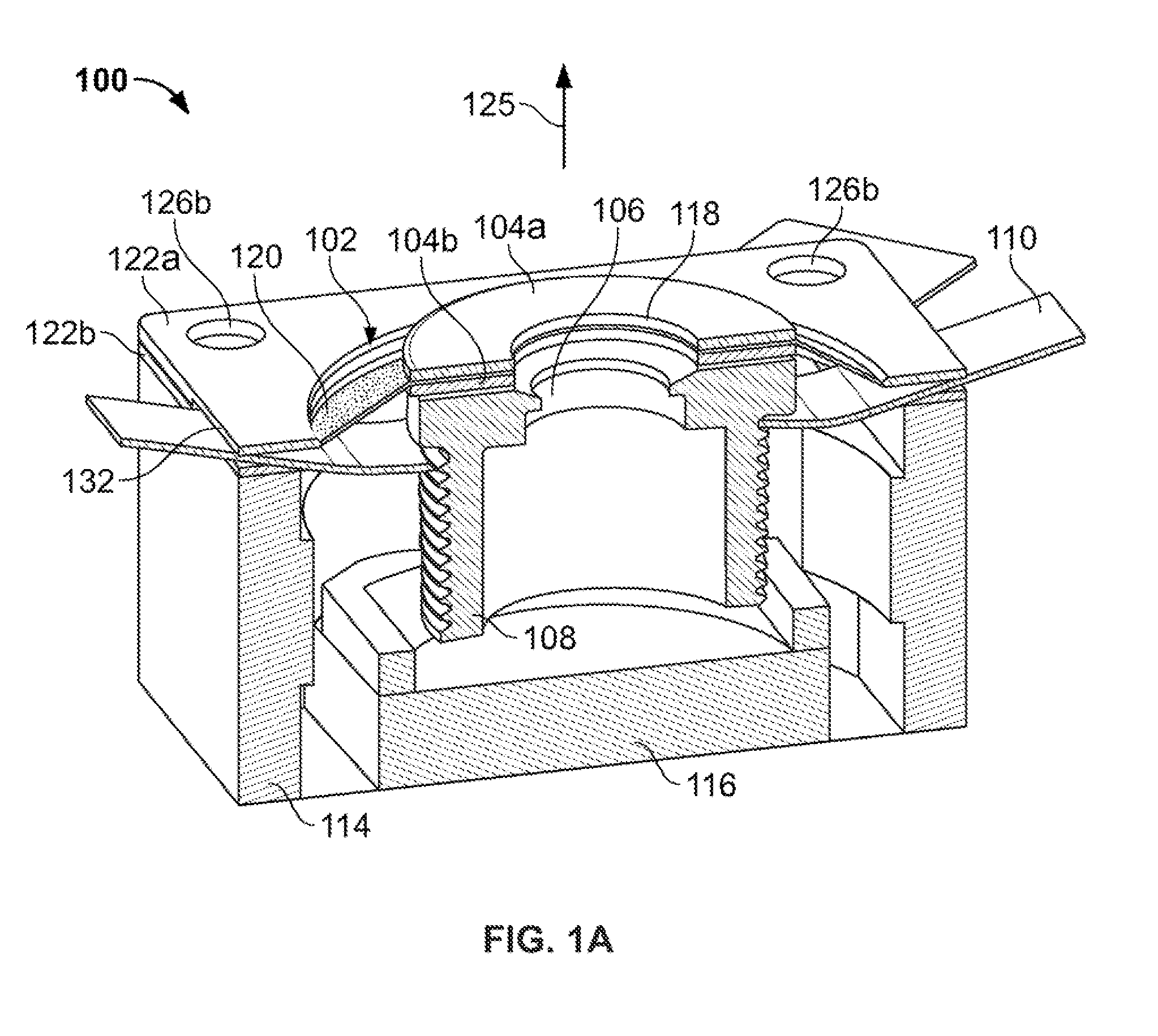
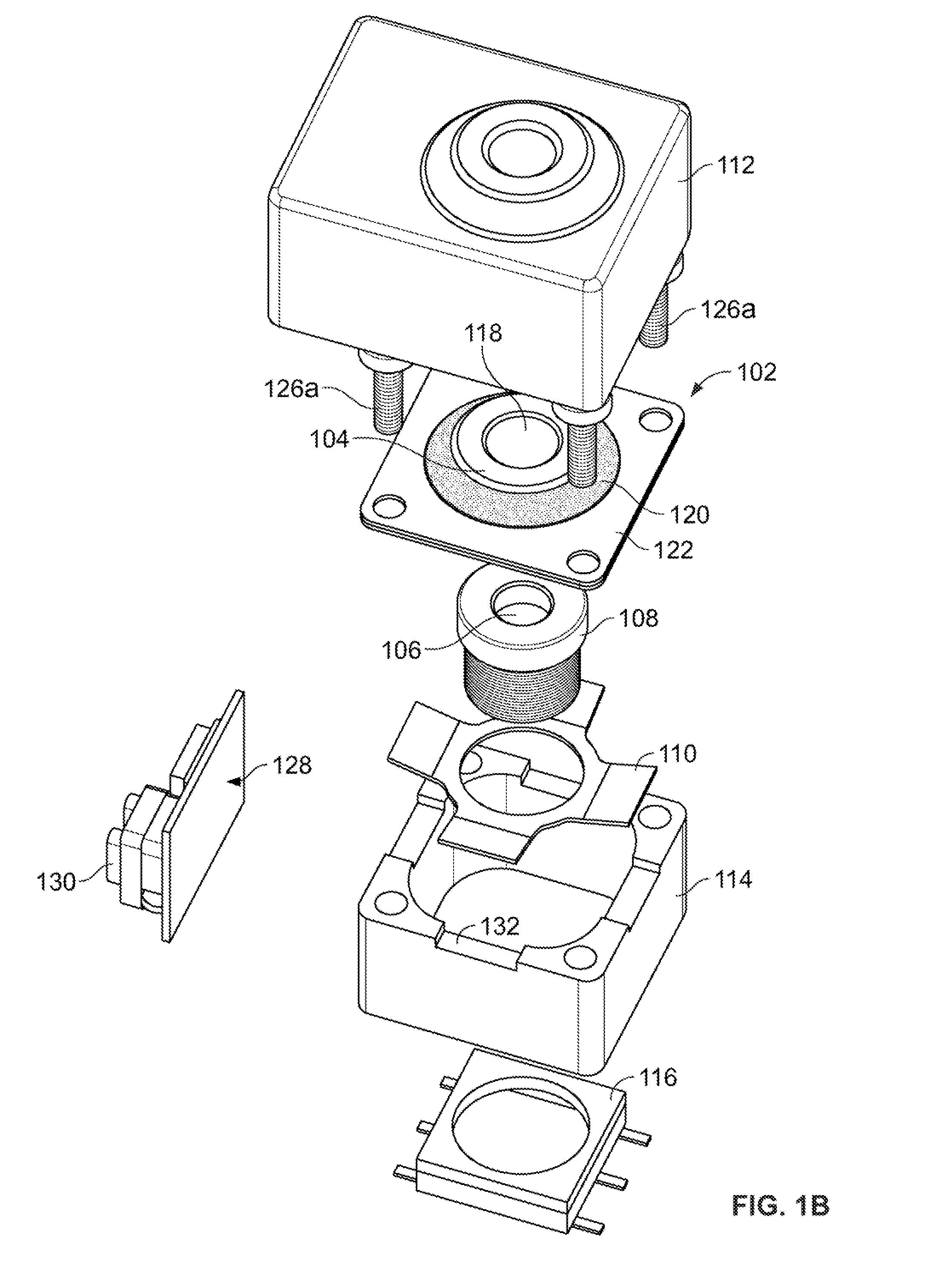
[0058]Referring now to the drawings, FIGS. 1A and 1B illustrate an optical lens system of the present invention having auto-focus capabilities. The figures detail a lens module 100 having a lens barrel 108 holding one or more lenses (not shown). An aperture 106 is provided at a dis...


PUM


Abstract

The present invention provides optical systems, devices and methods which utilize one or more electroactive polymer actuators to stabilize the image produced by the device or system.

Description

FIELD OF THE INVENTION[0001]The present invention relates to optical lens systems and, in particular, relates to such systems employing electroactive polymer transducers to adjust the lens to provide auto-focusing, zoom, image stabilization and / or shutter / aperture capabilities.BACKGROUND[0002]In conventional optical systems, such as in digital cameras, motors and solenoids are used as sources of power to displace gears and cams which act upon optical elements, e.g., lenses, to provide focusing, zoom, and image stabilization (also referred to as shake prevention). There are many disadvantages to such conventional systems—power consumption is high, response times are long, accuracy is limited and space requirements are high.[0003]Advancements in miniaturized technologies have led to high-quality, highly-functioning, light-weight portable devices, and an ever-increasing consumer demand for even further improvements. An example of this is the development of cellular telephones to includ...

Claims


Application Information

Patent Timeline
IPC IPC(8): H04N5/225
CPCG03B5/00
Inventor HEIM, JONATHAN R.POLYAKOV, ILYAZARRABI, ALIREZA
Owner BAYER MATERIALSCIENCE AG
Why Eureka
Try Eureka