
Multi-drop bus to personal computer interface

a technology of personal computer and drop bus, which is applied in the field of digital computer interfaces, can solve the problems of incompatibility of the multi-drop bus protocol of the vending industry with the personal computer interface protocol, the inability to interface standard vending equipment using the multi-drop bus to the personal computer, and the tediousness of having the same computer controller perform data polling as well as vending applications

Inactive Publication Date: 2006-03-02
SMOLEN CHRISTOPHER M +1
View PDF1 Cites 14 Cited by
  • Summary
  • Abstract
  • Description
  • Claims
  • Application Information

AI Technical Summary

Benefits of technology

This patent describes how to use an interface between a personal computer and another device (called a multi-drop bus) to communicate with each other more efficiently. By doing this, the personal computer can still function normally while being aware of what happens on the multi-drop bus. Additionally, if there are multiple devices connected to the multi-drop bus, it becomes possible for them to send data back and forth without interfering with one another's operations. Overall, this results in faster and better communication between different components within a system.

Problems solved by technology

The technical problem addressed by this patent is how to connect a personals computer to standard vending machines without compromising their performance or speed. Previous methods required complex hardware interfaces between the two systems, which resulted in slow processing times for the vending application.

Method used


Image

  • Multi-drop bus to personal computer interface
  • Multi-drop bus to personal computer interface
  • Multi-drop bus to personal computer interface

Examples


Embodiment Construction

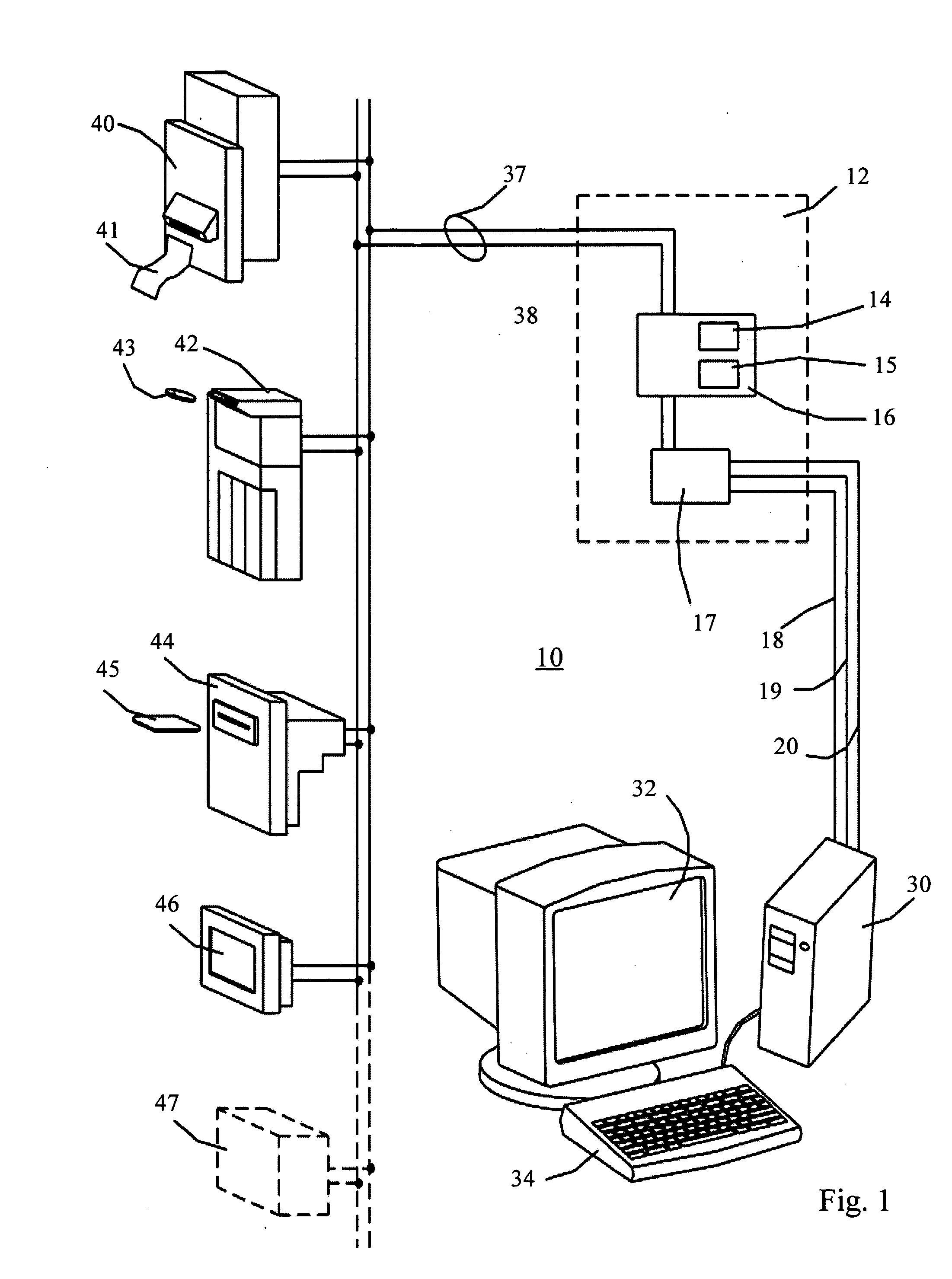
[0018] Referring now to FIG. 1, there is shown a personal computer enabled vending system 10 which includes a multi-drop bus to personal computer interface circuit 12, an industry standard multi-drop bus 37 and various vending devices 40,42,44,46,47, which may be connected to the Multi-Drop Bus 37. A Multi-Drop Bus compliant vending device may be a device such as a pliant currency acceptor 40, a coin mechanism 42, a smartcard reader 44, an output display 46, or a future device 47. The multi-drop bus to Personal computer interface 12 includes a multi drop bus to personal computer interface 16 and an RS-232, RS-232C, RS-485 or USB serial interface 17 that is connected to a serial port 21 of a standard personal computer 30.

[0019] The multi-drop bus to personal computer interface 16 indirectly links receive 38 and transmit 39 lines of the Multi-Drop Bus 37 to the personal computer 30. The multi-drop bus to personal computer interface 16 includes an embedded microprocessor 15 that has f...


PUM


Abstract

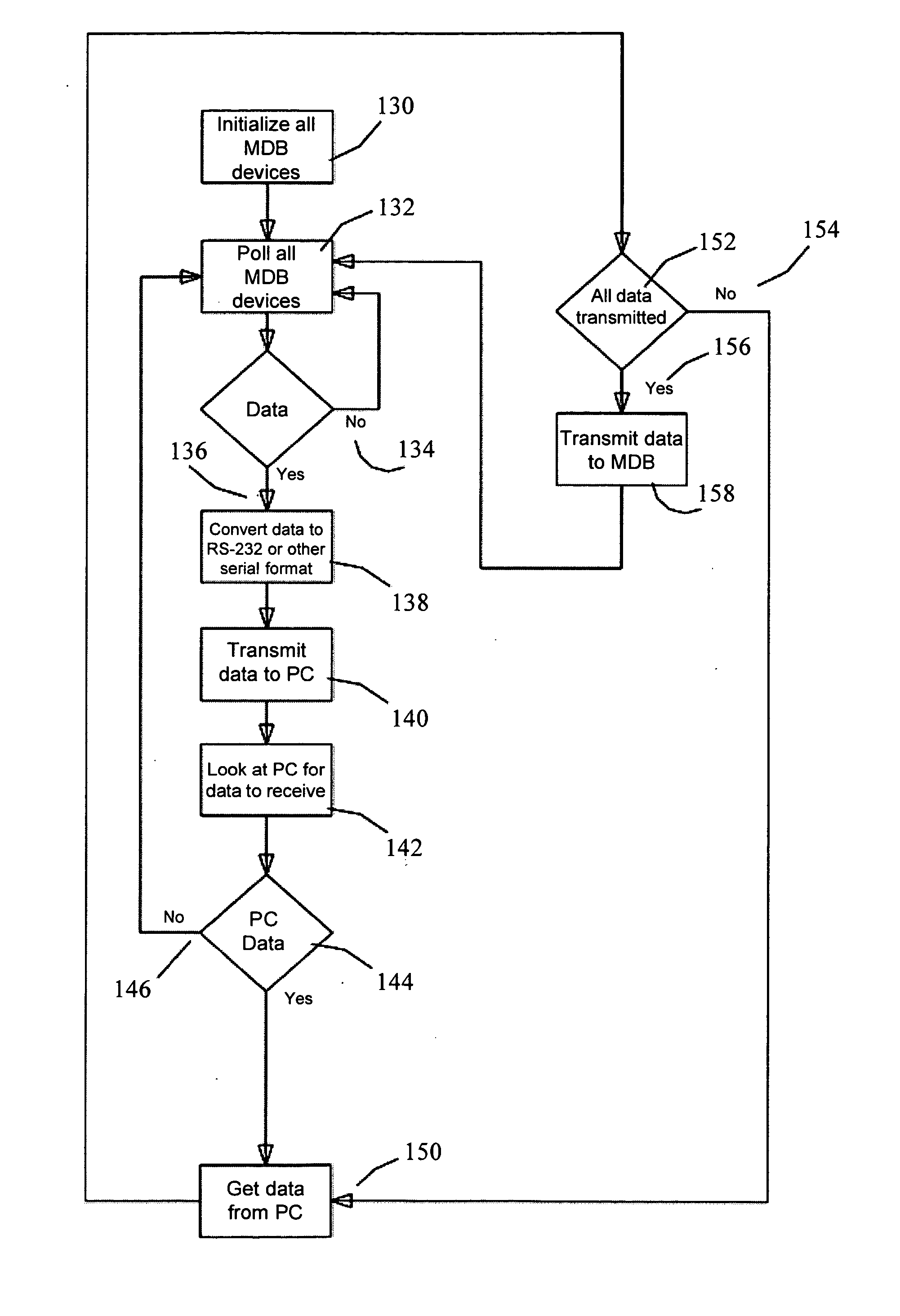
A Multi-Drop Bus to personal digital computer interface converts standard vending protocols into personal digital computer standards for RS-232, Universal Serial Bus (USB) and wireless Ethernet 802.11x protocols using framing transposition, modal management, and microprocessor based conversion algorithms.

Description


Claims


Application Information

Patent Timeline
Owner SMOLEN CHRISTOPHER M
Learn More