

Distributed request routing
a request routing and request technology, applied in the field of request routing methods, to achieve the effect of improving performance and more accurate load information
- Summary
- Abstract
- Description
- Claims
- Application Information
AI Technical Summary
Benefits of technology
Problems solved by technology
Method used
Image

Examples
first embodiment
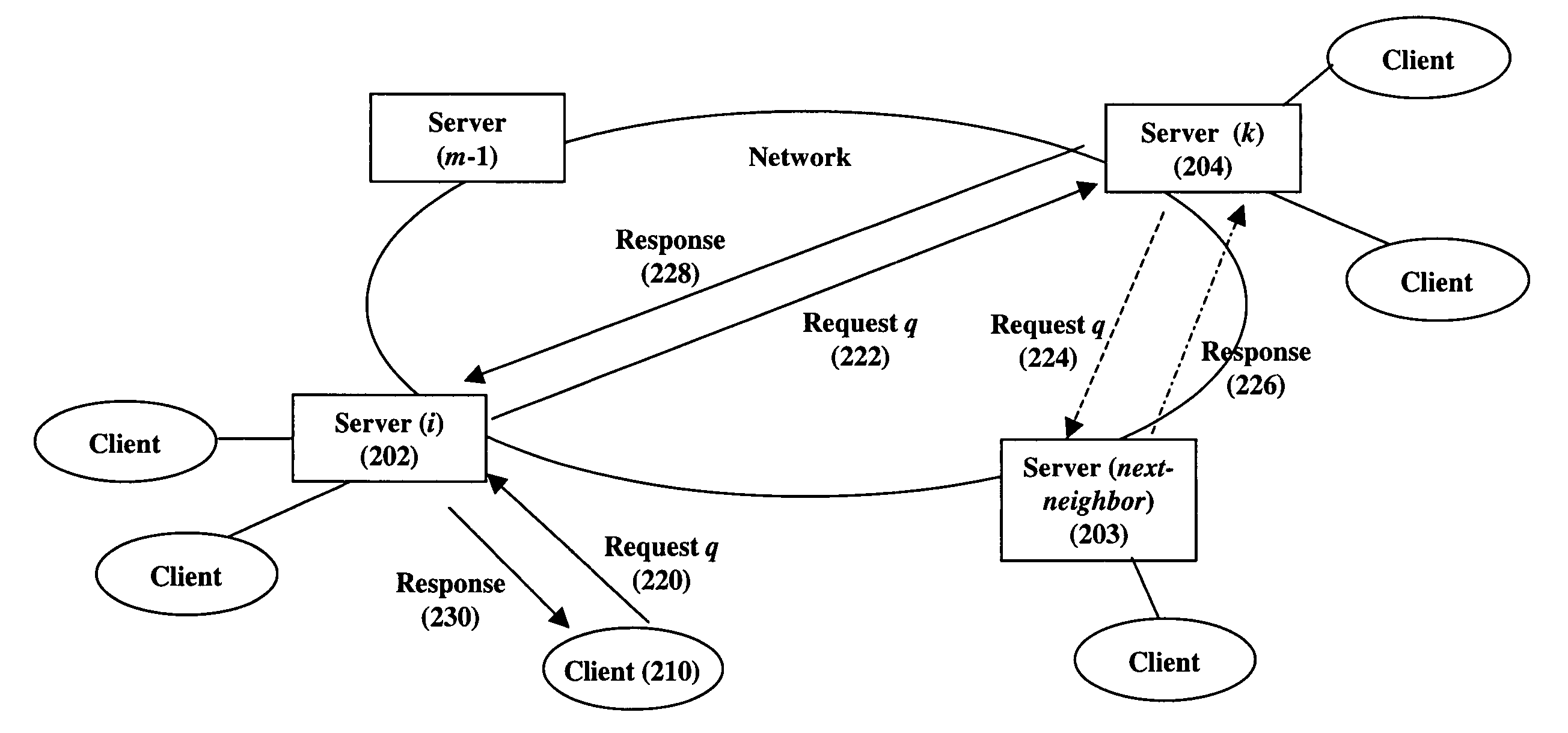
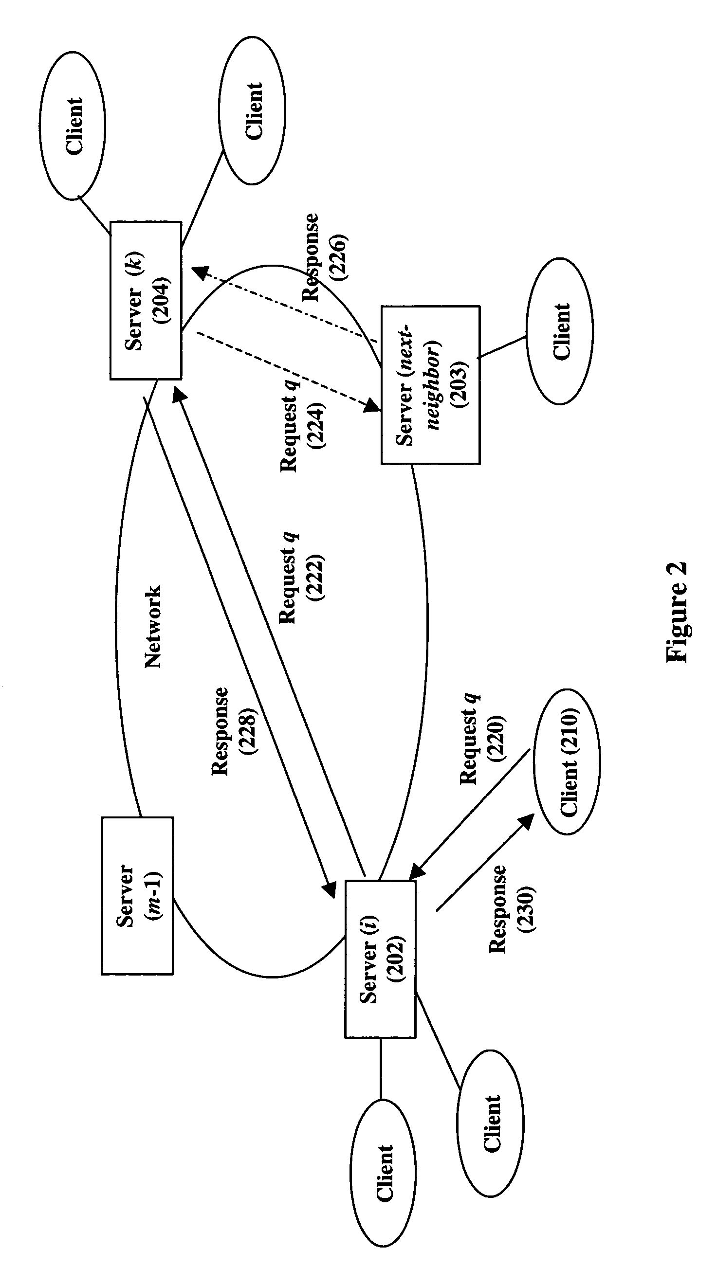
[0035] our invention for request-routing client requests among servers comprises three modules, as depicted by the method steps of FIGS. 3A, 3B, and 3C and as shown by the illustrative example of FIG. 2. For description purposes, it is assumed that all of the m servers that are part of the request routing method of our invention execute each of the three modules. Whether and when a server executes a given module depends on how it receives a given request q, as described below. Nonetheless, it should be understood that it is not necessary for each sever to execute all modules. For example, a server executes the method of FIG. 3A when initially receiving a client request. If a given server never receives initial client requests, it will not need to execute the method of FIG. 3A. In addition, whether the methods of FIGS. 3A, 3B, and 3C execute as one process or several processes on a given server is not specific to our invention.
[0036] Turning to the specific steps of the first embodim...
second embodiment
[0042] In accordance with our invention, when server k determines that its next-neighbor server 203 should process the request q (i.e., step 322), rather than forwarding the request q to the next-neighbor server 203 for processing in step 324, server k 204 informing server i 202 that the next-neighbor server 203 should process this request (i.e., steps 324 to 326 to 328 to 316 are bypassed). As such, from step 322 server k 204 immediately responds to server i by forwarding to it information regarding next-neighbor server 203. In response to receiving this information, server i directly forwards the request q to the next-neighbor server 203 and then waits for a response from server 203. Similar to above, when server 203 receives the request q, it processes the request and then forwards the response directly back to server i 202, which then returns the response to the client 210. Alternatively, server 203 can send the response directly to client 210.
[0043] Overall, note that in accord...
third embodiment
[0049] Reference will now be made to further embodiments of our invention. In accordance with our invention, an illustrative example of which is shown in FIG. 6, when the next-neighbor server 203 acts as a “second-chance server” and receives the service request q from server k 204, rather than executing the method of FIG. 3C and processing the request, it executes the method of FIG. 3B (in accordance with this embodiment of our invention, the method of FIG. 3C is not needed). More specifically, upon receiving a request q, the next-neighbor server 203 compares its current load to the constant Wnext-neighbor 203. If server 203's load is less than or equal to Wnext-neighbor 203, it is not overloaded and processes the service request q, forwarding the response back to client 210, either directly or through server k 204 and server i 202.
[0050] However, if the next-neighbor server 203 determines it is overloaded, it next determines if it should forward the request q to its next-neighbor s...
PUM
 Abstract
Description
Claims
Application Information