
Door which is intented to be positioned between the cockpit and the cabin of an aircraft

a technology for aircraft and cockpit, which is applied in the direction of door/window protective devices, wing accessories, transportation and packaging, etc., can solve the problems of insufficient ventilation of the restricted number of cockpit spaces, the gap between the door and its associated doorframe, and the inability to open the door on the cockpit side, etc., to achieve the effect of facilitating rapid disassembly and assembly of the trapdoor fitted with its associated locking/unlocking mechanism and greater security

Inactive Publication Date: 2006-03-09
AIRBUS OPERATIONS (SAS)
View PDF6 Cites 36 Cited by
  • Summary
  • Abstract
  • Description
  • Claims
  • Application Information

AI Technical Summary

Benefits of technology

[0011] More precisely, the purpose of the invention is to present a door with a design compatible with the measures mentioned above in order to increase the security of flight personnel located in the cockpit, while being capable of handling depressurisation occurring inside the aircraft, and more specifically depressurisation occurring inside the cabin of this aircraft.
[0051] The main body of the door and the trapdoor may be made from a bullet-proof material, to provide a door with even greater security for flight personnel.

Problems solved by technology

Furthermore, note that the fact that the door can be opened in two different ways usually creates a gap between the door and its associated doorframe.
However in this configuration, the doorframe is such that the door can only be opened on the cockpit side.
Furthermore, even if the venting areas can be provided between the cockpit and the cabin to achieve permanent venting between these two compartments of the aircraft, the restricted number of spaces available in the cockpit to accommodate these venting areas is not sufficient for satisfactory venting satisfying regulatory requirements related to aircraft cabin depressurisation cases.
Apart from respecting regulatory requirements, note that insufficient venting between this cockpit and the cabin can easily make it impossible to open this door and therefore blocking flight personnel inside the cockpit due to the difference in air pressure on each side of the door.
Finally, note that a higher difference in the air pressure can also cause severe equipment damage that could cause loss of the aircraft and / or injury to occupants of this aircraft.

Method used


Image

  • Door which is intented to be positioned between the cockpit and the cabin of an aircraft
  • Door which is intented to be positioned between the cockpit and the cabin of an aircraft
  • Door which is intented to be positioned between the cockpit and the cabin of an aircraft

Examples


Embodiment Construction

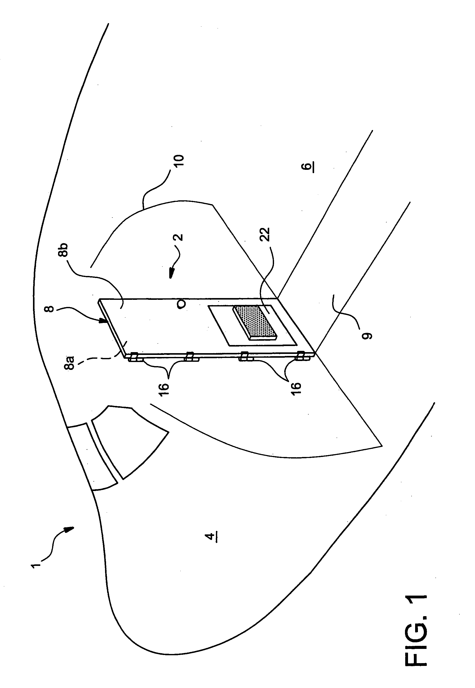
[0061]FIG. 1 shows a front part 1 of an aircraft provided with a door system 2 inserted between a cockpit 4 and a cabin 6, the door system 2 comprising a door 8 according to a preferred embodiment of this invention. Note that the door system 2 is arranged at a bulkhead 10 separating the cockpit 4 from the cabin 6, these two compartments being intended particularly to accommodate flight personnel in the cockpit, and aircraft passengers in the cabin.

[0062] The door 8, approximately in the shape of a parallelepiped and located perpendicular to a floor surface 9 of the aircraft, having a cockpit side 8a facing the cockpit 4 of the aircraft and a cabin side 8b facing the cabin 6 of the aircraft, when the door 8 is in a closed position like that shown in FIG. 1.

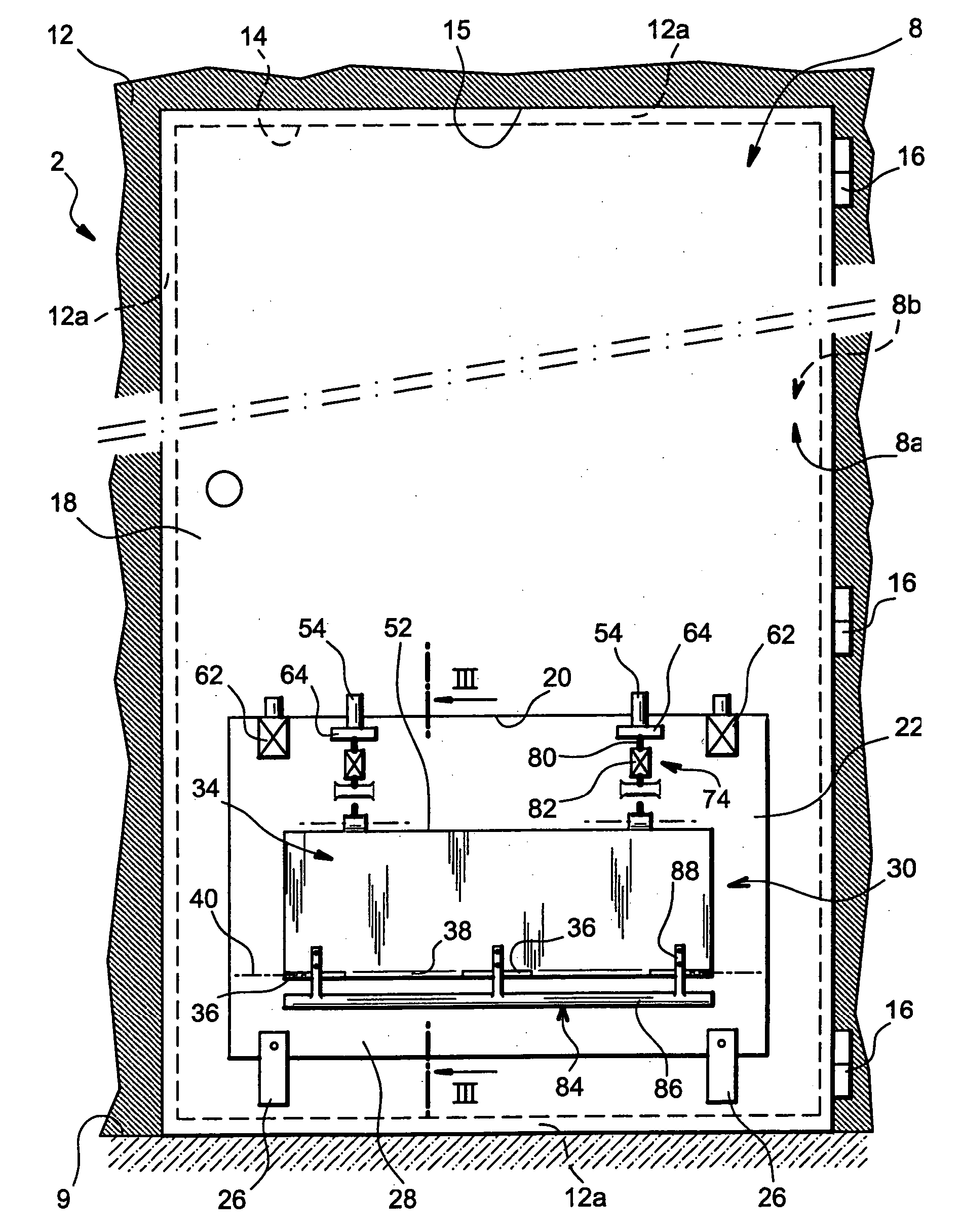
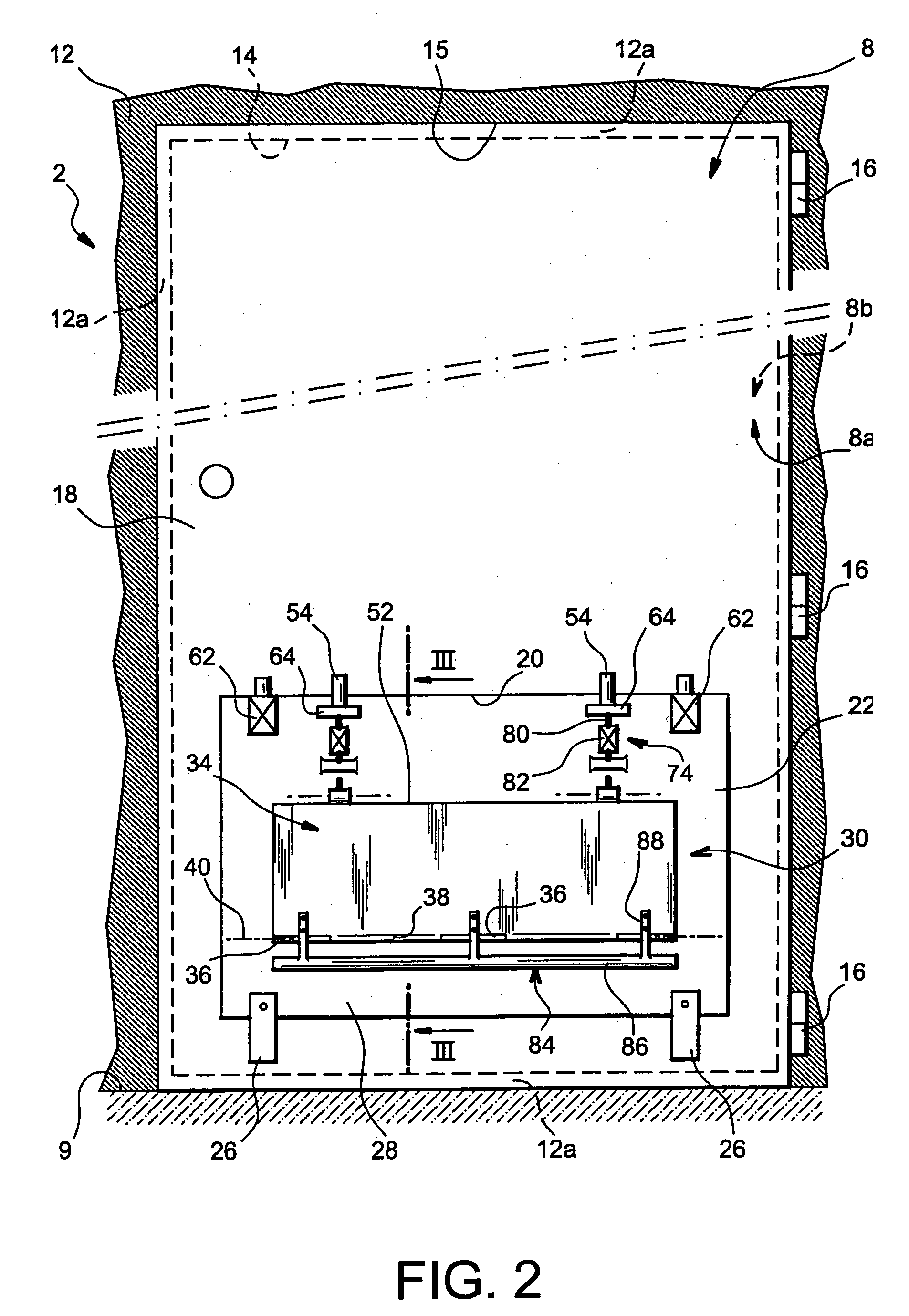
[0063] As can be seen more precisely in FIG. 2, the door system 2 comprises the door 8 and a doorframe 12, the doorframe defining a passageway 14 communicating between the cockpit 4 and the cabin 6 of the aircraft.

[0064] The doo...


PUM


Abstract

The invention relates to a door (8) designed to be inserted between a cockpit and a cabin of an aircraft, the door comprising a cockpit side (8a) and a cabin side (8b). According to the invention, the door comprises at least one trapdoor (22) capable of closing off a passageway (20) passing through the door and secondly being opened towards the cabin side, the door also comprising a locking / unlocking mechanism (30) of the trapdoor arranged on the cockpit side and that can automatically unlock the trapdoor when the difference between a cockpit pressure and a cabin pressure corresponding to the air pressures applied on the cockpit side and the cabin side of the door respectively is greater than a predetermined value.

Description

TECHNICAL DOMAIN [0001] This invention relates to a door designed to be inserted between a cockpit and a cabin of an aircraft, and a door system composed of such a door and an associated doorframe. STATE OF PRIOR ART [0002] In this technical domain, a conventional door is known that separates the cockpit and the cabin of an aircraft, this door normally being relatively simple in design and comprising a cockpit side facing the cockpit and a cabin side facing the cabin of the aircraft-when the door is in the closed position. [0003] Typically, the door is mounted on a doorframe so that the door can be opened indifferently towards the cockpit side or the cabin side. In this way, when depressurisation occurs in the cockpit of the aircraft the door can be opened towards the cockpit, and when depressurisation occurs in the cabin of the aircraft the door can be opened towards the cabin, to create venting between these two compartments. Furthermore, note that the fact that the door can be op...

Claims


Application Information

Patent Timeline
IPC IPC(8): E05C7/02B64C1/14B64D45/00E05B65/10
CPCB64C1/1407B64C1/1423E05B65/102B64D45/0015B64C1/1469B64C2001/009B64D45/0028
Inventor ROQUES, SERGEPUJOL, OLIVIERPROST, DOMINIQUEMALAVAL, PHILIPPE
Owner AIRBUS OPERATIONS (SAS)
Learn More