Rider restriction device of two-wheeled vehicle

a two-wheeled vehicle and restriction device technology, applied in the direction of vehicular safety arrangements, pedestrian/occupant safety arrangements, cycle equipment, etc., can solve the problem that the technology is not applicable to the vehicle, and achieve the effect of restricting the plastic deformation of the pad support member, and reducing the risk of accidents

Inactive Publication Date: 2006-03-09
HONDA MOTOR CO LTD
View PDF3 Cites 2 Cited by
  • Summary
  • Abstract
  • Description
  • Claims
  • Application Information

AI Technical Summary

Benefits of technology

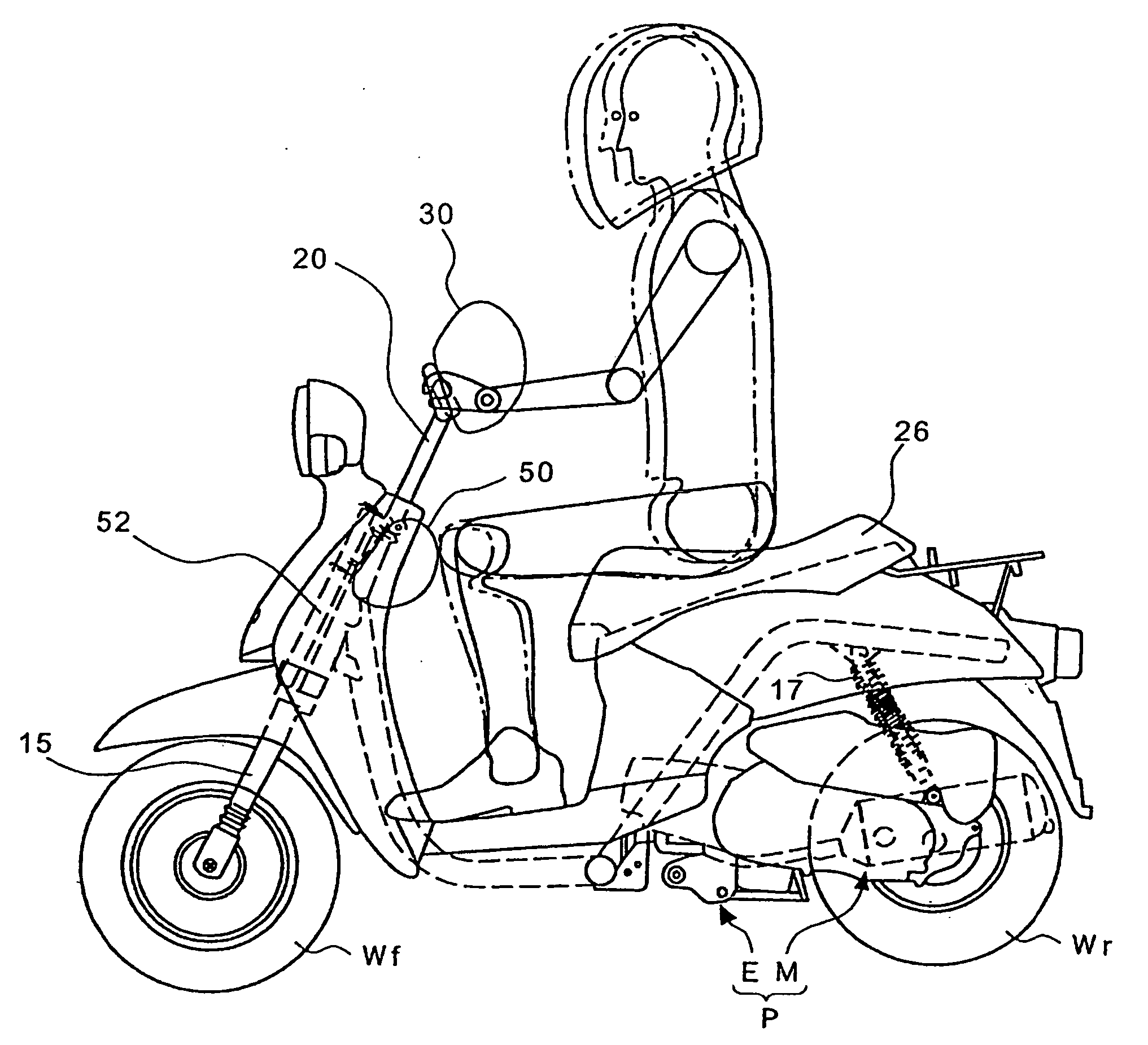
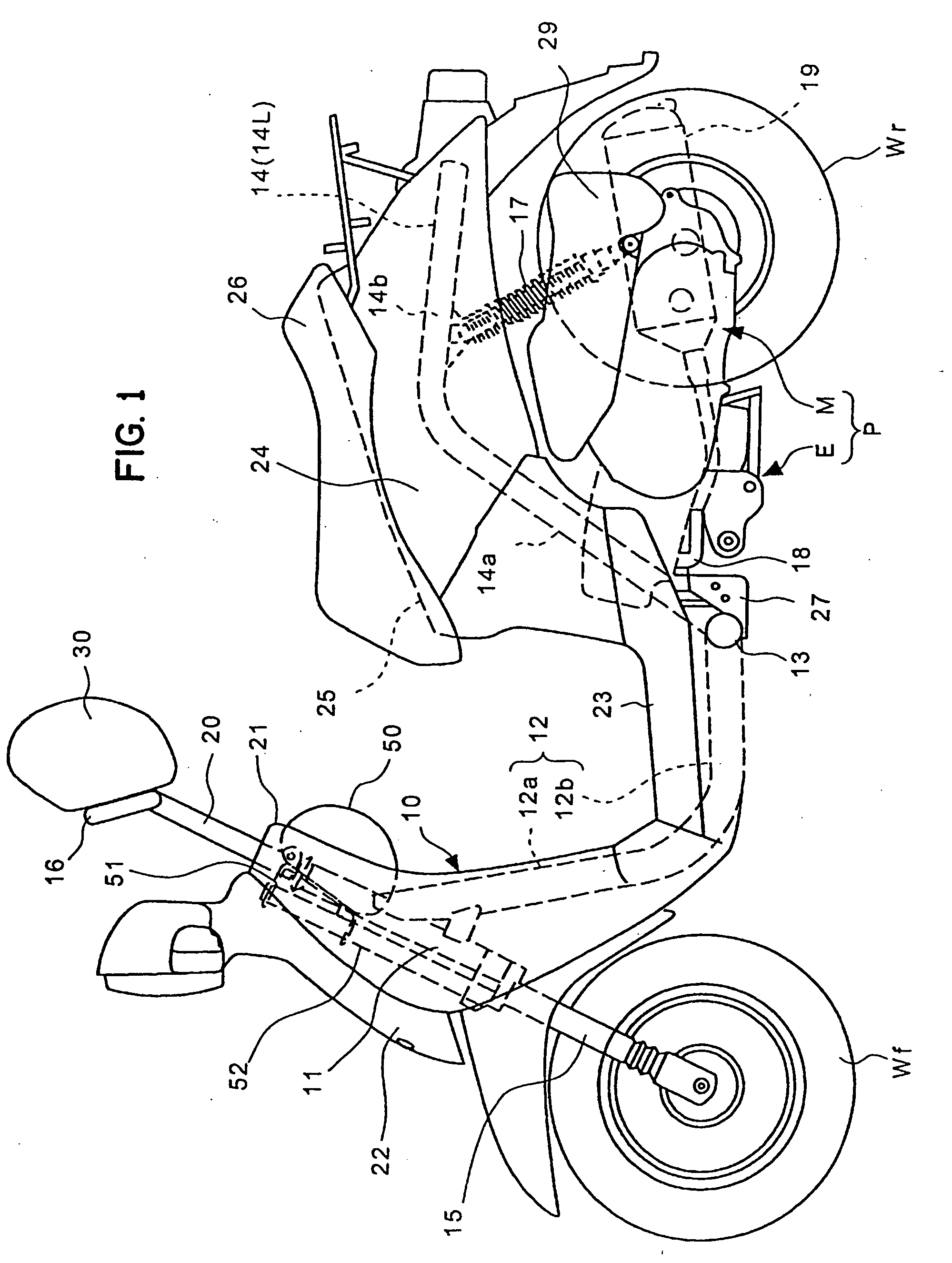
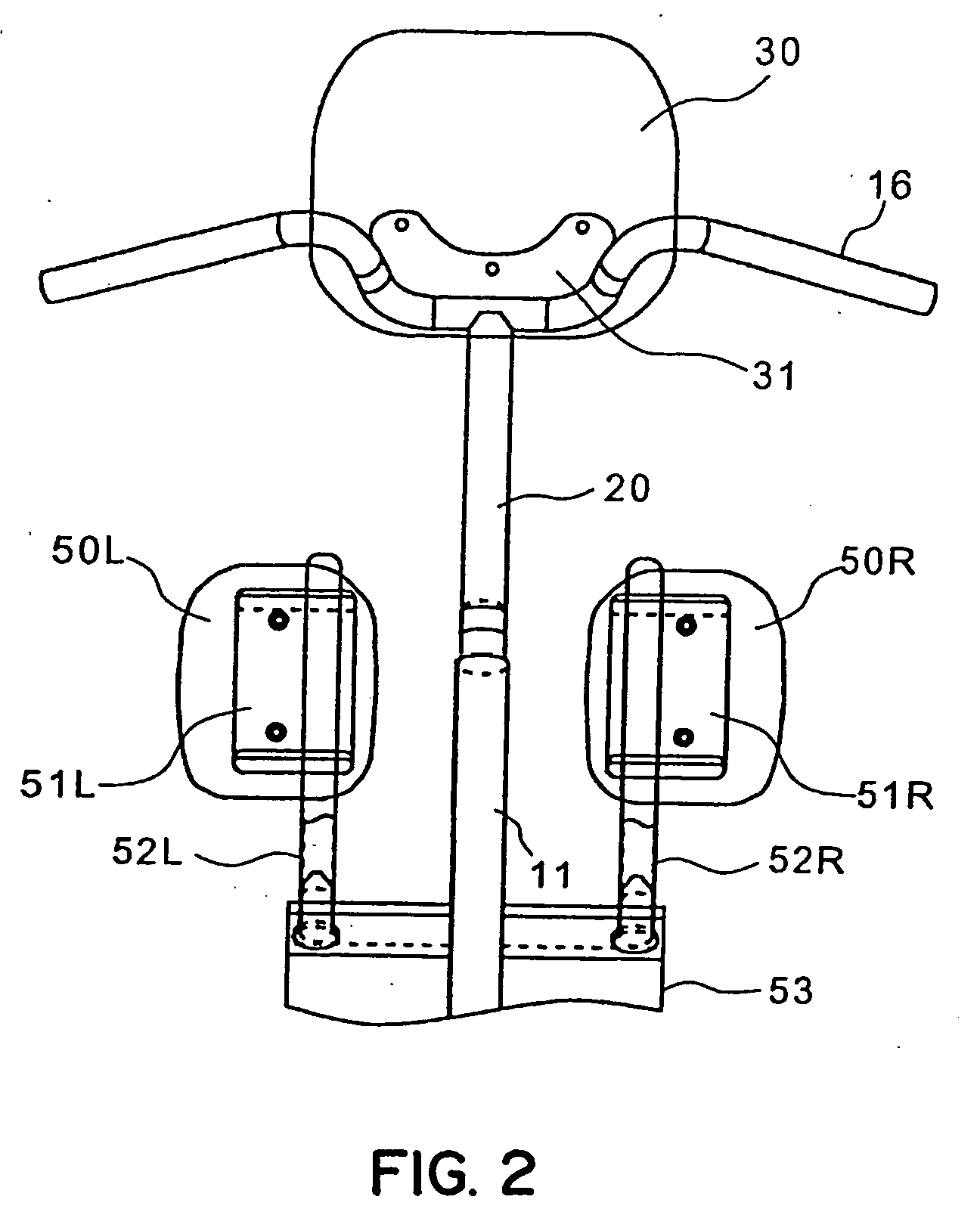
[0006] A rider restriction device is provided comprising a pair of left and right knee portion pads; a pipe-like pad support member which mounts the knee portion pads on one end side thereof; a fixing member which fixes another end side of the pad support member in a state that the knee portion pads face knee portions of the rider; and a load absorbing member which absorbs a forward load applied to the knee portion pads thus restricting the plastic deformation of the pad support member.
[0007] A portion of a load applied to the knee portion pad is consumed and absorbed by a load absorbing member and hence, the plastic deformation of the pad support member can be restricted. Accordingly, even when a frontward load in which a stress applied to the pad support member exceeds an elastic limit is applied to the knee portion pad, the frontward load is received whereby it is possible to surely restrict the rider.
[0008] The load absorbing member may comprise a collapse prevention member which restricts the collapse deformation of the pad support member. Therefore, it is possible to easily restrict the plastic deformation of the pad support member without applying a particular forming on the pad support member.
[0009] The load absorbing member may be a resilient member or a coil spring which is inserted into a plastic deformation portion of the pad support member. It may also be a bellows-like collapsible body which is formed on the pad support member. It is possible to restrict the plastic deformation of the pad support member by merely adding the resiliant member, the coil spring or the bellows-like collapsible body.
[0010] The fixing member may be a pipe-like connecting bar that is connected with another end side of the pad support member perpendicularly and extends in the lateral direction of a vehicle body, and the load absorbing member is a resilient member which is inserted in the inside of the connecting bar and restricts the torsional deformation of the connecting bar. In a constitution which imparts the elasticity to the pad support member by making use of a torsional stress of the connecting bar, it is possible to easily restrict the plastic deformation of the connecting bar.
[0011] The rider restriction device may further include a reinforcing member which restricts a front tilting amount of the pad support member. Since the front inclination amount of the handle connecting member can be restricted, it is possible to maintain the position of the restricting pad at a given height or more.

Problems solved by technology

The technique described in Japanese Patent 2705775 is proposed on the premise that a support member which supports the impact absorbing member is provided in front of the knee portions of the rider and hence, the technique is not applicable to a vehicle such as a motorcycle which has no support member in front of the knee portions of the rider.

Method used


Image

  • Rider restriction device of two-wheeled vehicle
  • Rider restriction device of two-wheeled vehicle
  • Rider restriction device of two-wheeled vehicle

Examples


first embodiment

[0033]FIG. 5 is a cross-sectional view of the above-mentioned load absorbing portion and symbols equal to the above-mentioned symbols indicate identical or similar portions. In this embodiment, the pad support pipe 52 has a lower end portion thereof fixed to a connecting member 53 in a state that the lower end portion is inserted in and penetrates the connecting member 53, while a longitudinal elastic member 55 penetrates in and is fixed to the inside of the lower end portion.

[0034] In such a constitution, when a frontward load which exceeds a given reference value is applied to the above-mentioned knee portion pad 50, the above-mentioned pad support pipe 52 starts a deflection thereof. When a stress exceeds a yielding point of the pad support pipe 52, the plastic deformation starts and, as indicated by a chain line in the drawing, the pad support pipe 52 starts bending in the frontward direction.

[0035]FIG. 11 shows the relationship between a frontward moving amount of the above-me...

second embodiment

[0037]FIG. 6 is a cross-sectional view of the above-mentioned load absorbing portion and symbols equal to the above-mentioned symbols indicate identical or similar portions. In this embodiment, the pad support pipe 52 has a lower end portion thereof fixed to a connecting member 53 in a state that the lower end portion is inserted in and penetrates the connecting member 53, while a coil spring 56 penetrates in and is fixed to the inside of the lower end portion.

[0038] In such a constitution, when a frontward load which exceeds a given reference value is applied to the above-mentioned knee portion pad 50, the above-mentioned pad support pipe 52 starts a deflection thereof. When a stress exceeds a yielding point of the pad support pipe 52, the plastic deformation starts and, as indicated by a chain line in the drawing, the pad support pipe 52 starts bending in the frontward direction. However, in this embodiment, since the coil spring 56 is inserted into the inside of a bent portion of...

third embodiment

[0039]FIG. 7 is a cross-sectional view of the above-mentioned load absorbing portion and symbols equal to the above-mentioned symbols indicate identical or similar portions. In this embodiment, the pad support pipe 52 has a lower end portion thereof fixed to a connecting member 53 in a state that the lower end portion is inserted in and penetrates the connecting member 53, while a bellows-like collapsible body 57 is formed in the vicinity of an upper portion of the connecting member 53.

[0040] In such a constitution, when a frontward load which exceeds a given reference value is applied to the above-mentioned knee portion pad 50, the above-mentioned pad support pipe 52 starts a deflection thereof. When a stress exceeds a stress limit of the bellows-like collapsible body 57, a front portion side of the bellows-like collapsible body 57 is collapsed and the plastic deformation in which a lower portion side of the bellows-like collapsible body 57 extends starts and hence, the pad support...


PUM


Abstract

The present invention provides a rider restricting device of a two-wheeled vehicle which is easily applicable to a small-sized vehicle and, at the same time, can absorb a frontward load and alleviate a load applied to a rider.

Description

FIELD OF THE INVENTION [0001] The present invention relates to a rider restriction device of a two-wheeled vehicle, and more particularly to a rider restriction device of a two-wheeled vehicle which restricts a lower half part of a rider from moving in the forward direction of the vehicle body. BACKGROUND OF THE INVENTION [0002] Japanese Patent 2705775 discloses a technique for restricting a lower half part of a rider from moving toward a front portion of a vehicle body in a four-wheeled automobile that arranges an impact absorbing member on a lower portion of an instrument panel cabin and at a position which faces knees of the rider. [0003] The technique described in Japanese Patent 2705775 is proposed on the premise that a support member which supports the impact absorbing member is provided in front of the knee portions of the rider and hence, the technique is not applicable to a vehicle such as a motorcycle which has no support member in front of the knee portions of the rider. ...

Claims


Application Information

Patent Timeline
Patent Type & Authority Applications(United States)
IPC IPC(8): B62M1/00B62J27/00
CPCB60R21/04B62J27/00B60R2021/0088B60R2021/0051B62K11/00
Inventor TSUNODA, KAZUHIKOKURATA, NORIHIROAKIYAMA, HIDEAKIMURATA, YUTAKAOGINO, TAKASHI
Owner HONDA MOTOR CO LTD
Why Eureka
Try Eureka