

Pixel interpolation circuit, pixel interpolation method and image reader
a pixel interpolation circuit and image reader technology, applied in image enhancement, instruments, image data processing, etc., can solve the problems of conventional pixel interpolation circuit and image quality degradation
- Summary
- Abstract
- Description
- Claims
- Application Information
AI Technical Summary
Benefits of technology
Problems solved by technology
Method used
Image

Examples
embodiment 1
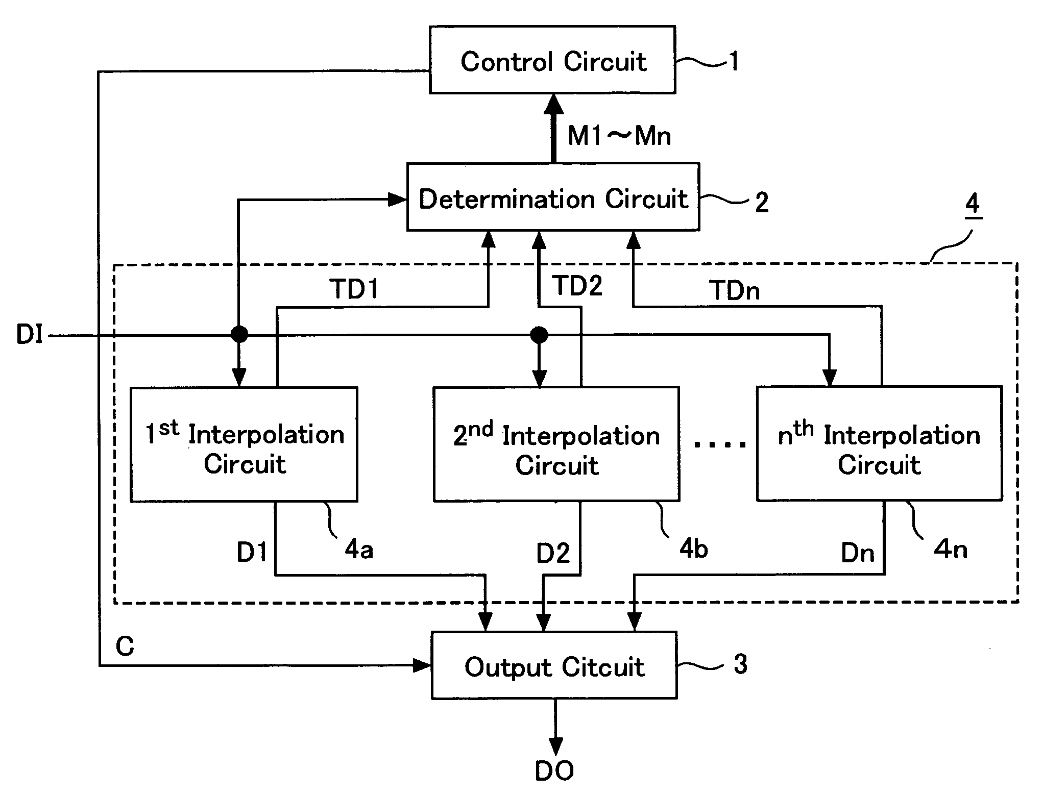
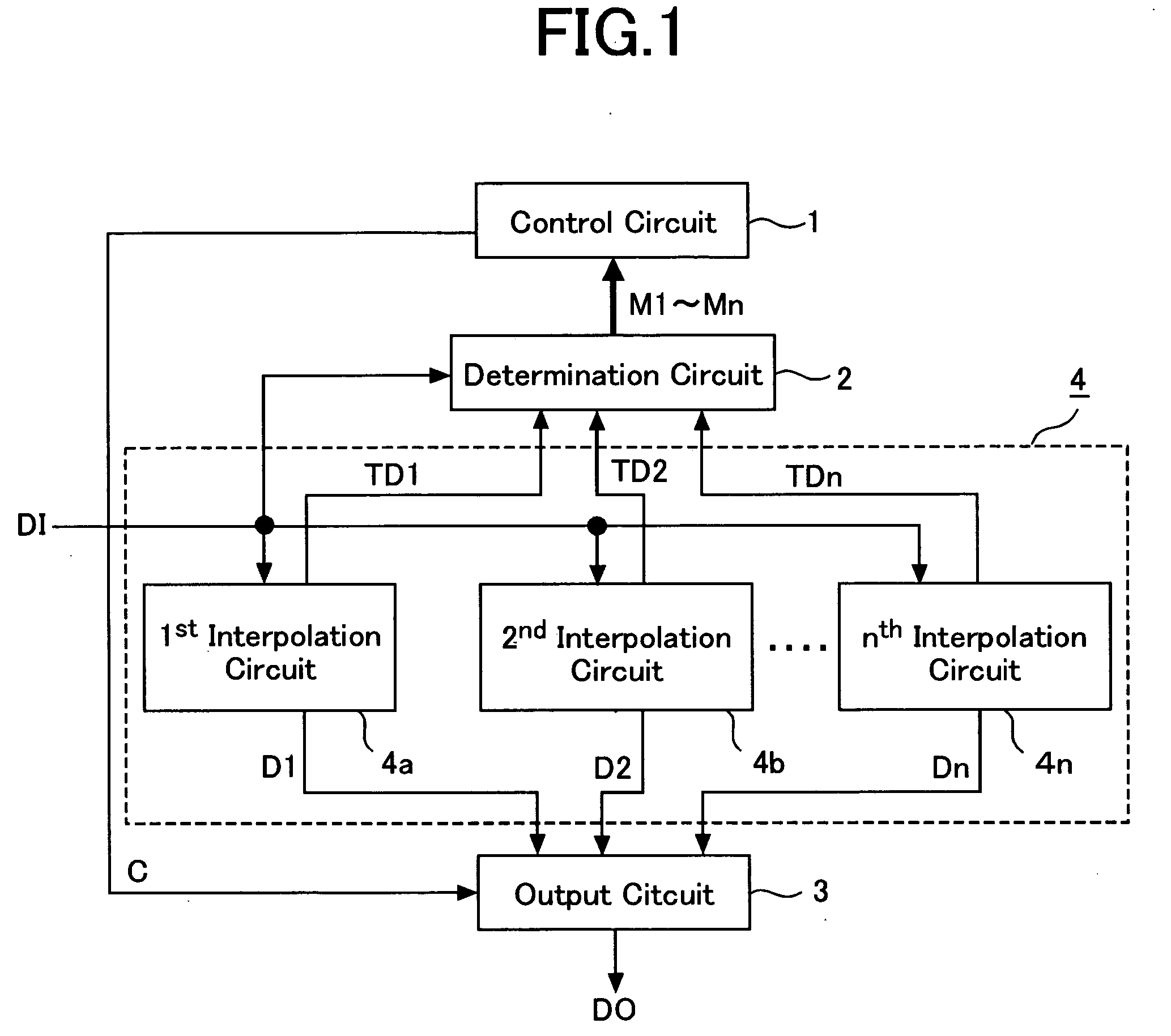
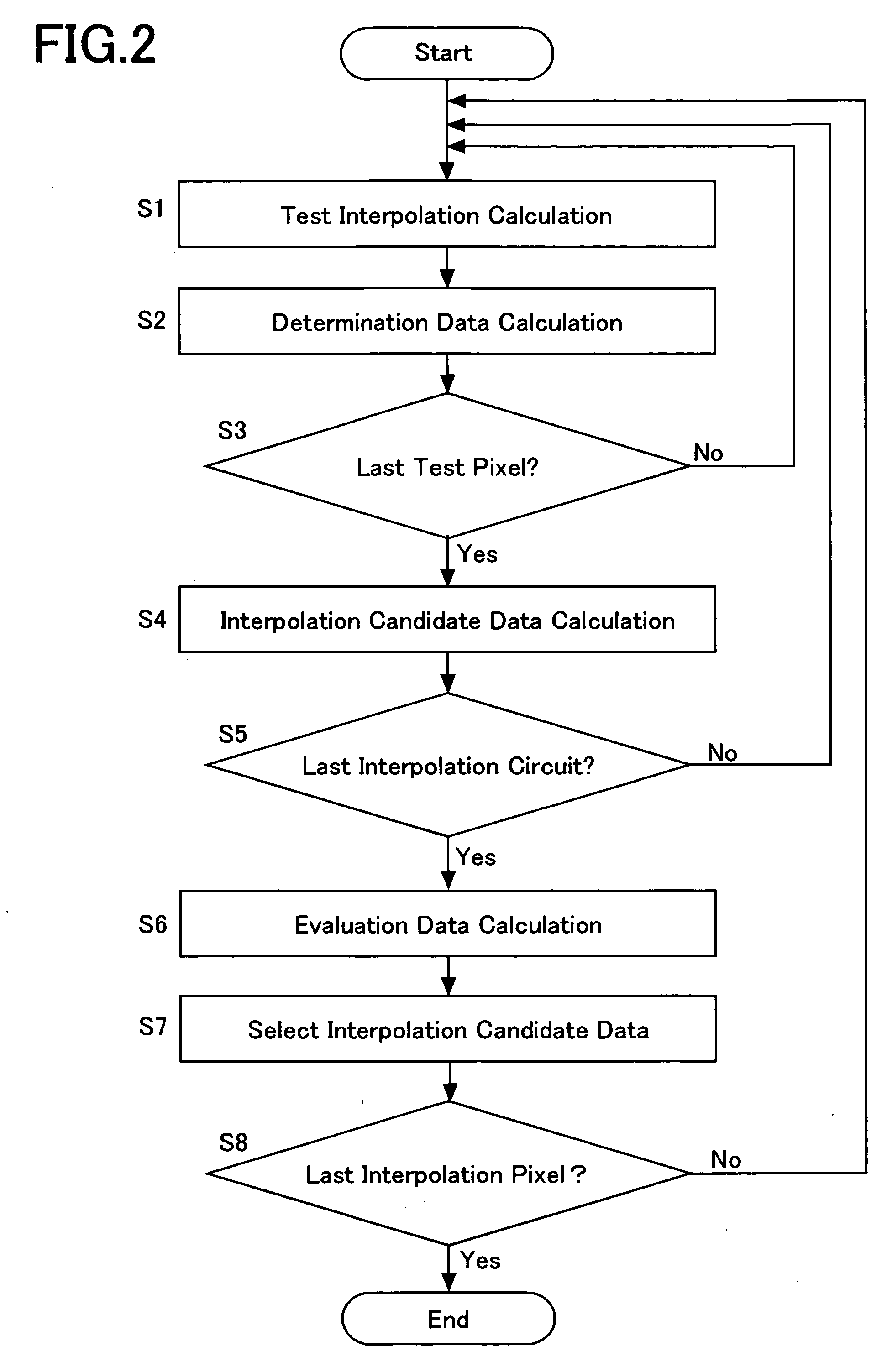
[0029]FIG. 1 is a block diagram illustrating a configuration of a pixel interpolation circuit according to this invention. The pixel interpolation circuit illustrated in FIG. 1 includes a control circuit 1, a determination circuit 2, an output circuit 3, and an interpolation unit 4. The interpolation unit 4 includes 1st-nth interpolation circuits 4a-4n (n is an integer greater than 2), each of which performs different interpolation processes. Image data D1 read by a scanner or a copy machine is sent to the determination circuit 2 and the interpolation unit 4. The image data D1 sent to the interpolation unit 4, is sent to each of the 1st-nth interpolation circuits 4a-4n. FIG. 2 is a flow chart illustrating a process of the pixel interpolation performed by the pixel interpolation circuit illustrated in FIG. 1.
[0030] Firstly, in the 1st interpolation circuit 4a, a test interpolation calculation is performed over pixels T1-Tm (hereinafter, referred to as test pixels) neighboring one of...
embodiment 2
[0083]FIG. 15 is a block diagram illustrating another configuration of the interpolation unit 4. The interpolation unit 4 of the pixel interpolation circuit illustrated in FIG. 1 includes a left / right averaging interpolation circuit 5, a rightward up averaging interpolation circuit 6, and a leftward up averaging interpolation circuit 7. The left / right averaging interpolation circuit 5 and the rightward up averaging interpolation circuit 6 calculate the test interpolation data and the interpolation candidate data using the methods described in the Embodiment 1.
[0084] The leftward up averaging interpolation circuit 7 calculates average values of pixels located on the leftward up and rightward down positions of a pixel to be interpolated. In other words, the circuit calculates the average value “XL” of pixels “A” and “F” located on the leftward up and rightward down positions of the pixel L. The average value XL calculated by the leftward up averaging interpolation circuit 7 is repres...
embodiment 3
[0112] Data amount of the determination data to be processed in the determination circuit 2 may be increased when the number of the interpolation circuits composing the interpolation unit 4 is increased. The data amount of the determination data can be decreased, by binarizing or ternarizing the determination data using a predefined threshold value.
[0113] As an example, a method of ternarizing the determination data values will be explained.
[0114] The determination circuit 2 compares the absolute value of the difference between the test interpolation data TD1[T1] calculated by the first interpolation circuit 4a and the value DI[T1] of the test pixel T1, with two predefined threshold values TH1 and TH2 (0≦TH12). When the absolute value is smaller than the threshold value TH1, a value of the determination data M1[T1] is set −1; when the absolute value is larger than the threshold value TH1 and smaller than the threshold value TH2, a value of the determination data is set 0; and when...
PUM
 Abstract
Description
Claims
Application Information