Shake correction control apparatus and imaging apparatus using same shake correction control apparatus

Inactive Publication Date: 2006-03-09
KONICA MINOLTA PHOTO IMAGING
View PDF6 Cites 27 Cited by
  • Summary
  • Abstract
  • Description
  • Claims
  • Application Information

AI Technical Summary

Benefits of technology

[0024] According to this configuration, when the control value has once been changed, the control value

Problems solved by technology

Nevertheless, this driving sound causes various problems.
For example, in a place like a museum and an exhibition hall where silence is requested, the driving sound of the camera shake correction mechanism can cause

Method used


Image

  • Shake correction control apparatus and imaging apparatus using same shake correction control apparatus
  • Shake correction control apparatus and imaging apparatus using same shake correction control apparatus
  • Shake correction control apparatus and imaging apparatus using same shake correction control apparatus

Examples


first embodiment

1. First Embodiment

[0041]

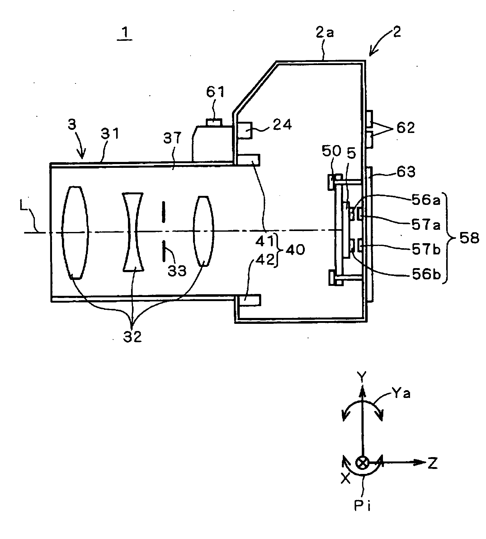
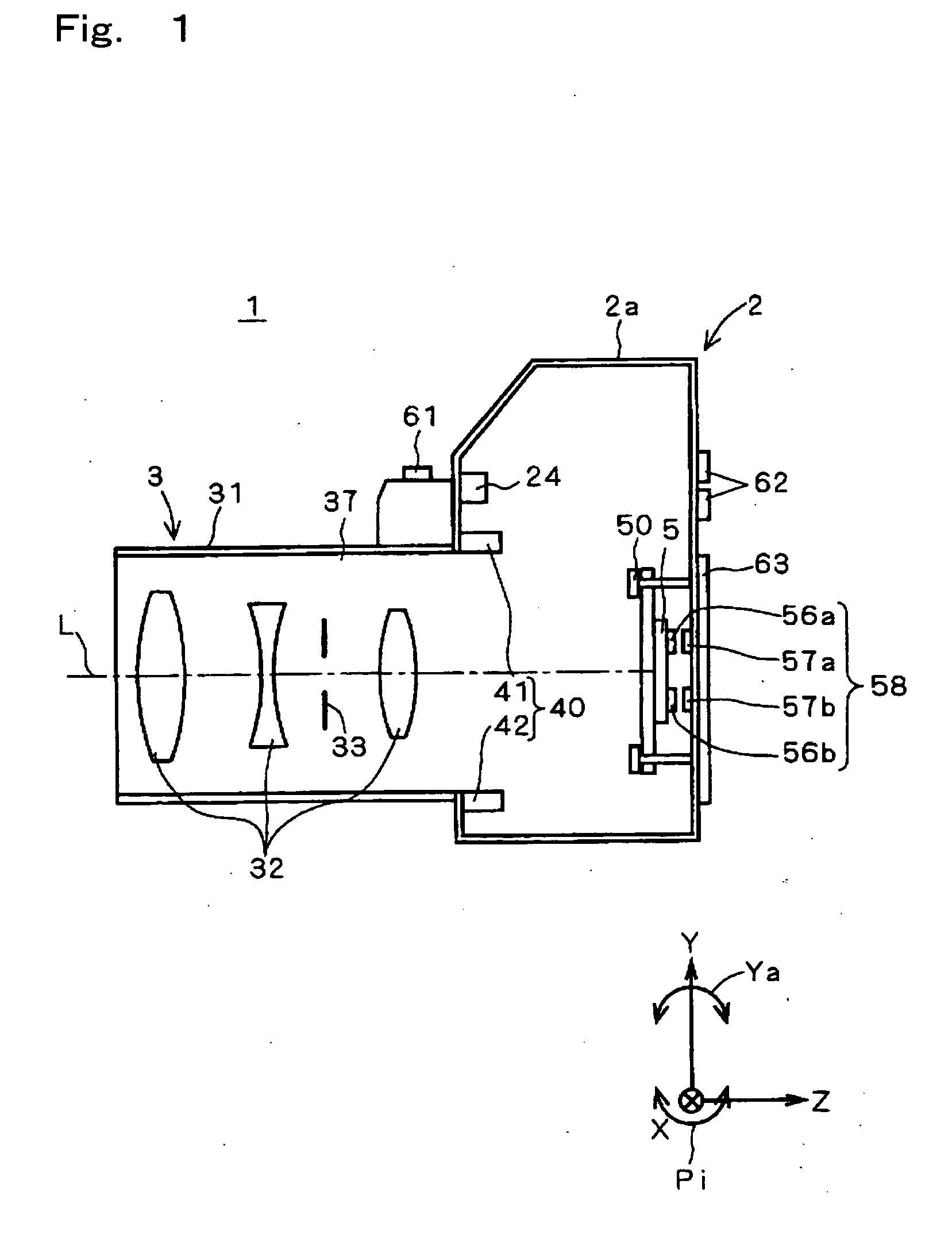
[0042]FIG. 1 is a sectional view showing the main configuration of a digital camera 1 serving as an imaging apparatus according to an embodiment of the invention. The digital camera 1 has a camera shake correction function for correcting (suppressing) a blurring of the object image in the image caused by a camera shake. As shown in the figure, in a general view, the digital camera 1 comprises: a camera body section 2; and a taking lens 3 fixed to a housing 2a of the camera body section 2.

[0043] In the following description, the three-dimensional XYZ orthogonal coordinate system shown in the figure is appropriately used for specifying the direction and orientation. Here, the Z axis aligns with the optical axis L of the taking lens 3, while the positive direction of the Z axis indicates the direction of propagation of incident light (right-hand direction in the figure). The Y axis is in the vertical direction, while the positive direction of the Y axis indica...

second embodiment

2. Second Embodiment

[0094] Next, a second embodiment of the invention is described below. The configuration and the processing of the digital camera 1 of the present embodiment are almost the same as those of the first embodiment. Thus, the following description is given with focusing attention on the difference. In the camera shake correction processing of the first embodiment, the function (“electric current value changing function”, hereafter) of changing the drive current value in the electric current value control section 74 has always been activated, so that the “camera shake correction performance” and the “silence performance” have been changed appropriately. Nevertheless, in a possible case, a user desires that either the “camera shake correction performance” or the “silence performance” should be maximized always. Thus, the digital camera 1 of the present embodiment allows the user to set up whether the “camera shake correction performance” and the “silence performance” ar...

third embodiment

3. Third Embodiment

[0106] Next, a third embodiment of the invention is described below. The configuration and the processing of the digital camera 1 of the present embodiment are almost the same as those of the first embodiment. Thus, the following description is given with focusing attention on the difference. In the first embodiment, the threshold value to be compared with the environmental sound level has been fixed. Nevertheless, in the case that the threshold value is fixed, when the environmental sound level fluctuates across the threshold value in the vicinity of the threshold value, the “camera shake correction performance” and the “silence performance” are changed at each time that the environmental sound level passes the threshold value. This causes frequent changes in the driving sound level, and hence can cause a problem that for example, the change phenomenon itself in the driving sound level serves as a noise. Thus, in the electric current value setting processing of t...


PUM


Abstract

The imaging apparatus of the invention comprises: image pickup means for acquiring as an image a part of region of an optical image formed by a taking lens; camera shake correcting means for changing a relative position between the part of region and the optical image depending on a vibration of the imaging apparatus, and thereby suppressing a shake of the object image in the image; state detecting means for detecting a state of an environment where the imaging apparatus is located; and changing means for changing a control value of the camera shake correcting means which influences a driving sound level of the camera shake correcting means, depending on the state of environment. According to this configuration, the control value of the camera shake correcting means is changed depending on the state of environment. This permits appropriate balance between the silence performance and the camera shake correction performance.

Description

[0001] This application is based on Japanese Patent Application No. 2004-258083 filed in Japan on 6 Sep. 2004, the entire content of which is hereby incorporated by reference. FIELD OF THE INVENTION [0002] The present invention relates to an imaging apparatus comprising camera shake correcting means for suppressing a shake (blurring) of an object image in an image. DESCRIPTION OF RELATED ART [0003] In general, when an imaging apparatus held solely by human hands is used to take an image of a photographic object, a minute vibration occurs in the imaging apparatus so that the optical axis of the taking lens moves relative to the photographic object. Thus, a shake (blurring) called a “camera shake (in-the-hand shake)” occurs in the object image in the acquired image. [0004] In the prior art, an imaging apparatus such as a digital camera has been known that employs a camera shake correction mechanism for correcting such a camera shake. In such a camera shake correction mechanism, a plur...

Claims


Application Information

Patent Timeline
IPC IPC(8): G03B17/00
CPCG03B5/02G03B2207/005H04N5/23287H04N5/23248H04N5/2253H04N23/54H04N23/68H04N23/687
Inventor OGINO, AKIRA
Owner KONICA MINOLTA PHOTO IMAGING
Why Eureka
Try Eureka