Street sweeper with dust control

a street sweeper and dust control technology, applied in the field of street sweepers, can solve the problems of excessive vacuum in the plenum and the area, and achieve the effect of being ready to clean

Inactive Publication Date: 2006-03-16
ENGEL GREGORY J +1
View PDF26 Cites 79 Cited by
  • Summary
  • Abstract
  • Description
  • Claims
  • Application Information

AI Technical Summary

Benefits of technology

[0007] The general purpose of the present invention is to provide a street sweeper having dust control from two or more cleaning heads with one air vacuum source in a road sweeper, as well as a dust filtration system which can be readily cleaned on site without the removal of filtration components and without other extraordinary measures. The present invention can be incorporated for use along a substantially planar surface, such as a road where the term road can mean any surface within a manufacturing facility, such as a tiled or concrete paved surface or the like, and can also be utilized along a common roadway. In the present invention, a single fan is mounted to a plenum in the upper region of a truck-mounted hopper to provide vacuum for dust control. A filter mechanism and a filter shaker mechanism mount just below the fan in the upper region of the plenum. The bottom of the plenum includes an orificed plenum array having a plurality of automatic flexible airflow operated flap valves which are closed during the sweeping operation to seal the bottom of the plenum.

Problems solved by technology

Subsequent to the sweeping operation and when cleaning of the filter mechanism is required, power to the fan is stopped, thereby influencing the vacuum integrity of the plenum causing the cessation of vacuum in the plenum and the areas or regions with which the vacuum communicates.

Method used


Image

  • Street sweeper with dust control
  • Street sweeper with dust control
  • Street sweeper with dust control

Examples


Embodiment Construction

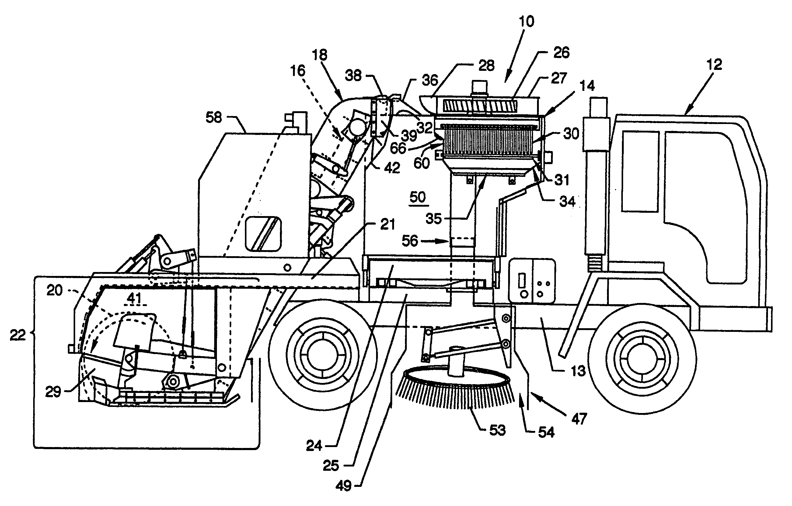
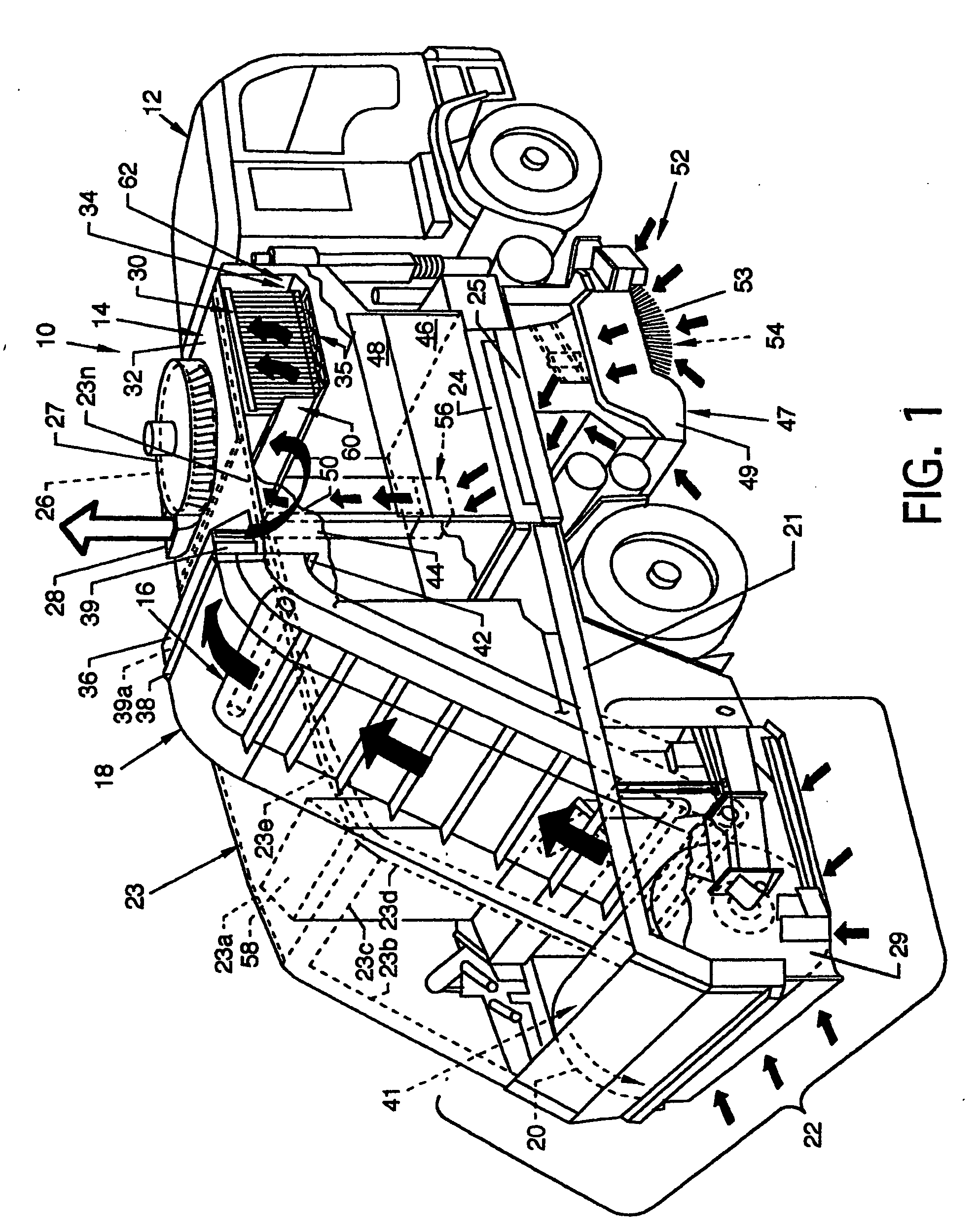
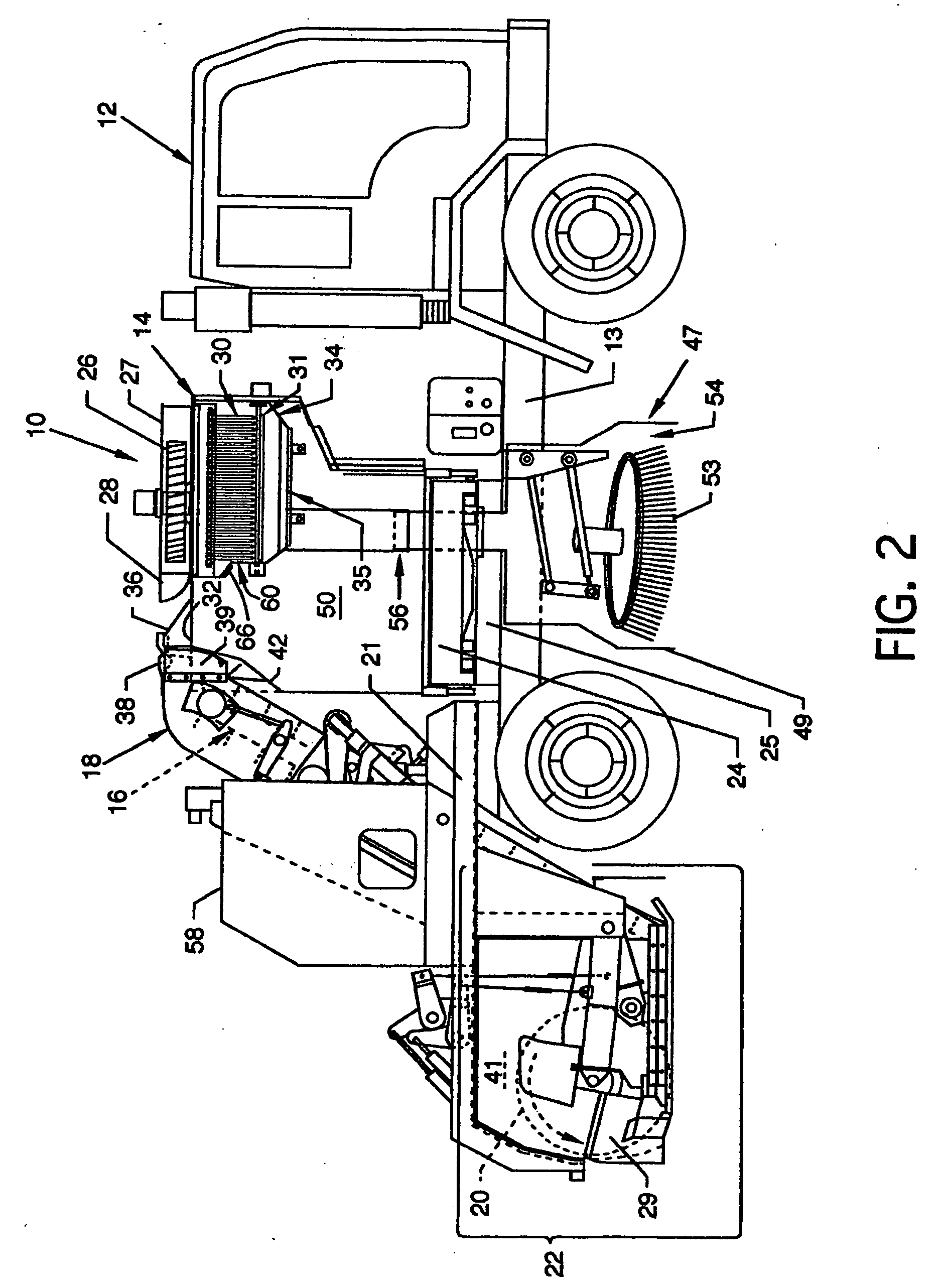
[0028]FIG. 1 illustrates a cutaway overview of the street sweeper 10, the present invention, having dust control from two or more cleaning heads with one air source. Major components and other components complementary to the street sweeper are mounted to and secured to the frame or chassis 13 (FIG. 2) of a truck 12 or are mounted elsewhere at other locations about the invention. Major components of the invention include a vacuum source, such as a fan 26, a fan shroud 27, a hopper 14, a plenum 34, an orificed plenum array 35, a plurality of one-piece flap valves 37a-37n (FIG. 3), a filter mechanism 30 including a filter 33 and other components which provides for support and function thereof, and a filter shaker mechanism 31 (FIG. 2), the majority of which connect associatively with other major members and components of the street sweeper 10 including a gutter broom assembly 52 having a right gutter broom 53 and a left gutter broom (not shown), a gutter cleaning head 47 including a cl...


PUM


Abstract

Street sweeper having dust control from two or more cleaning heads with one air source where one fan provides vacuum for a centrally located rotating broom which is surrounded by a vacuumized chamber and for a gutter broom which is surrounded by a vacuumized chamber. A plenum having a unique valving system and a filter shaker mechanism provides for filter cleaning and for a dirt and debris path from the plenum to a hopper bottom during filter cleaning.

Description

CROSS REFERENCES TO RELATED APPLICATIONS [0001] None. BACKGROUND OF THE INVENTION [0002] 1. Field of the Invention [0003] The present invention pertains to a street sweeper, and more particularly, to dust control from two or more cleaning heads with one air source. [0004] 2. Description of the Prior Art [0005] Prior art dust control systems for road sweepers frequently include the use of water which wets the debris and dirt on the road surface to prevent dust from becoming airborne during the sweeping process. In such systems, water must be provided at various sweeper locations, such as, but not limited to, the main rotary broom and the gutter brooms. Water systems often just wet down debris and dirt whereby the wetted debris and dirt may still reside on the wetted roadway after sweeping rather than having been carried into the conveyor or hopper. The use of vacuum systems instead of water systems to carry off generated airborne dust is often desirable in that no wetted debris or di...

Claims


Application Information

Patent Timeline
Patent Type & Authority Applications(United States)
IPC IPC(8): E01H1/08
CPCE01H1/0854
Inventor ENGEL, GREGORY J.OLSONOSKI, THEODORE J.
Owner ENGEL GREGORY J
Why Eureka
Try Eureka