Drive mechanism of a zoom lens

a technology of drive mechanism and zoom lens, which is applied in the direction of mountings, instruments, camera body details, etc., can solve the problems of excessive spring load, difficult to apply a stable biasing spring force to each movable frame, and become a great burden on the operation of the zoom lens, so as to achieve stable biasing spring force and avoid excessive spring load on the movable frame

Inactive Publication Date: 2006-03-16
ASAHI KOGAKU KOGYO KK
View PDF8 Cites 20 Cited by
  • Summary
  • Abstract
  • Description
  • Claims
  • Application Information

AI Technical Summary

Benefits of technology

[0008] The present invention provides a drive mechanism for driving a plurality of optical elements of a zoom lens, wherein the drive mechanism can exert a stable biasing spring force to each of a plurality of movable frames which respectively support the plurality of optical elements without increasing the spring load on the movable frames excessively. The present invention further provides a drive mechanism for driving a plurality of optical elements of a zoom lens, wherein the installation of biasing springs and the setting (adjustment) of the biasing force thereof are easy to carry out.
[0021] According to the present invention, the drive mechanism can exert a stable biasing spring force to each of the plurality of movable frames without increasing the spring load on the movable frames excessively with a simple structure. Moreover, the workability of installing the biasing springs and the workability of balancing the biasing spring force of the biasing springs are improved.

Problems solved by technology

However, the biasing spring forces of the biasing springs vary due to the difference in amount of movement among the movable frames including the aforementioned one or more external barrels, which makes it difficult to apply a stable biasing spring force to each movable frame.
For instance, since the minimum biasing force among variations in the biasing spring force exerted on the movable frames needs to be determined as a reference spring load (minimum return force), the spring load grows excessively upon the spring biasing force becoming maximum, and may become a great burden on operations of the zoom lens.
As a result, in the case of a motor-driven zoom lens, a zoom motor thereof needs to be a large type producing a strong torque, which makes it difficult to achieve miniaturization and weight reduction of the zoom lens.
However, using such a biasing spring makes it difficult to assemble the zoom lens.
Additionally, in this structure it is difficult to achieve the balance between the two biasing springs.

Method used


Image

  • Drive mechanism of a zoom lens
  • Drive mechanism of a zoom lens
  • Drive mechanism of a zoom lens

Examples


Embodiment Construction

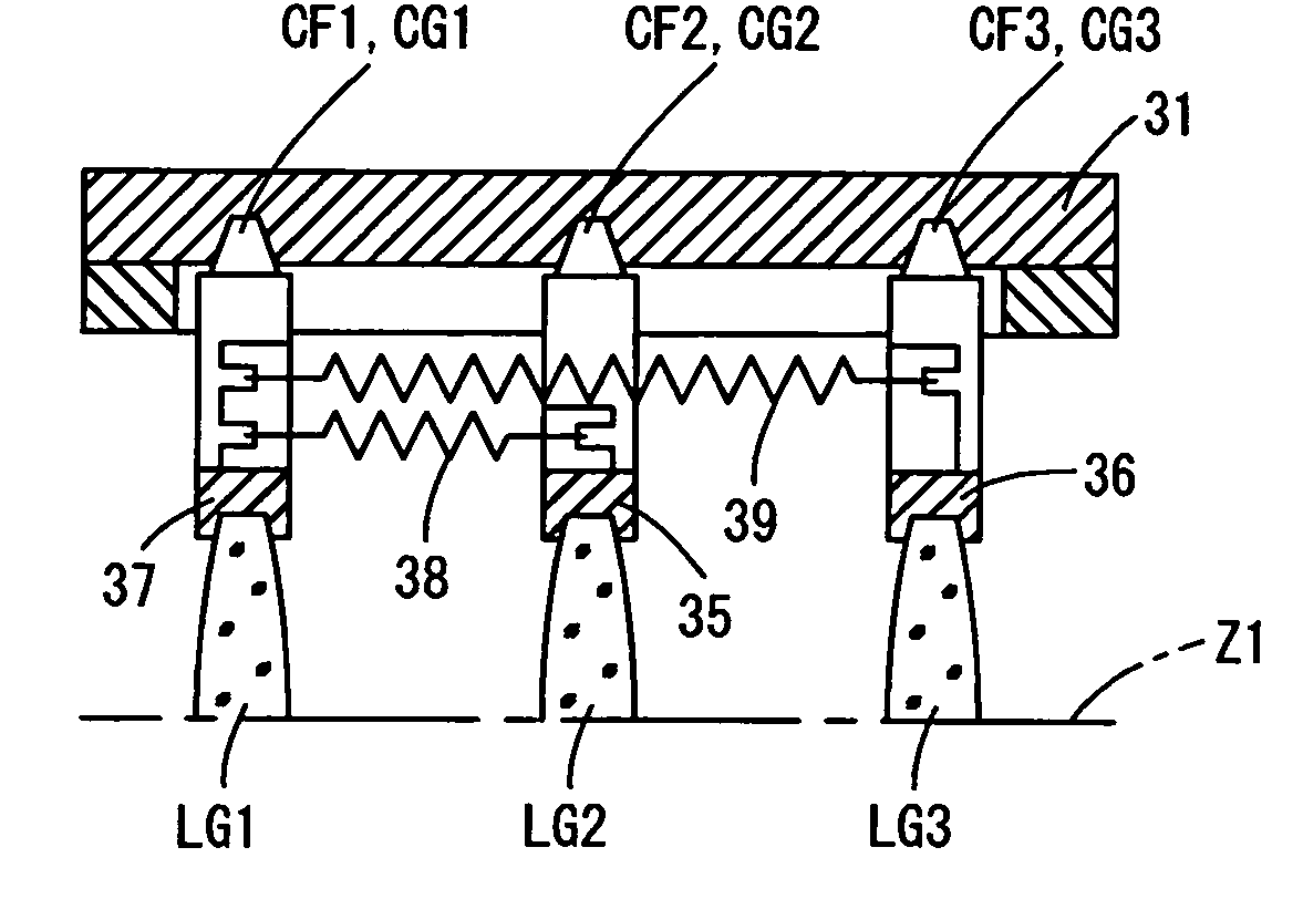
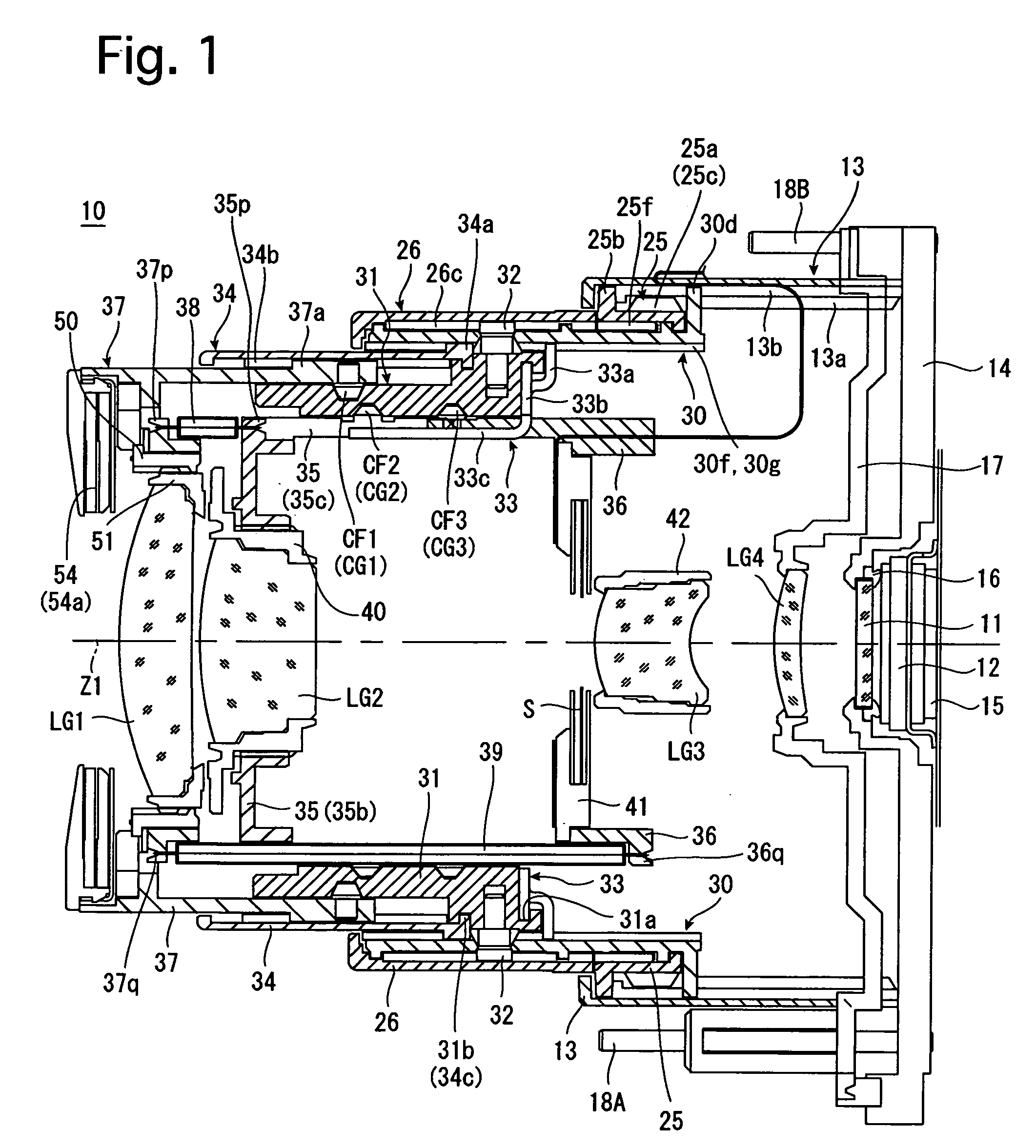
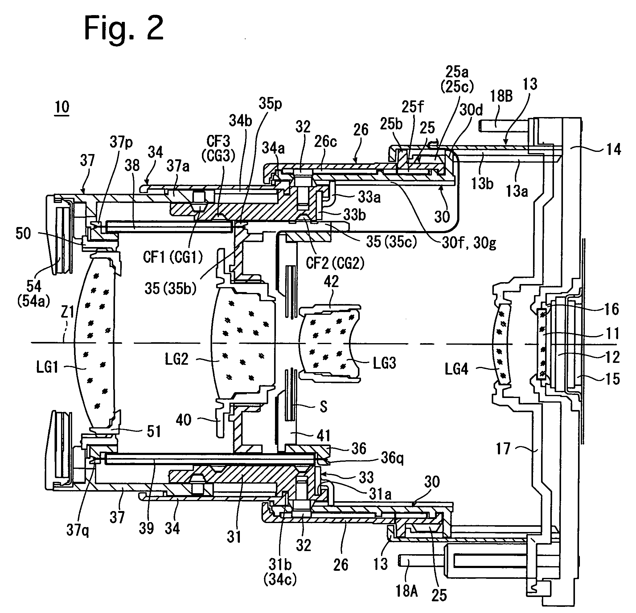
[0061]FIGS. 1 through 3 show an embodiment of a zoom lens according to the present invention in different states. FIG. 1 shows a state of the zoom lens 10 at the wide-angle extremity, FIG. 2 shows a state of the zoom lens 10 at the telephoto extremity, and FIG. 3 shows a state of the zoom lens in a retracted position (fully retracted position). The zoom lens 10 is incorporated in a digital camera (the camera body thereof is not shown in the drawings). As shown in FIGS. 1 and 2, the photographing optical system of the zoom lens 10 in a ready-to-photograph state of the zoom lens 10 consists of a first lens group LG1, a second lens group LG2, a shutter S, a third lens group LG3, a fourth lens group LG4, a low-pass filter (optical filter) 11, and a CCD image sensor (solid-state image pick-up device) 12. The first lens group LG1, the second lens group LG2 and the third lens group LG3 are driven along a photographing optical axis Z1 in a predetermined moving manner to perform a zooming op...


PUM


Abstract

A drive mechanism of a zoom lens includes three movable members which support optical elements, including a front movable member, an intermediate movable member and a rear movable member; a common driving member including a driving device for moving the three movable members independently; and a biasing member including first and second spring members which bias the three movable members to remove backlash. One of the front movable member and the rear movable member serves as a common-engaging spring support member to which one end of each of the first and second spring members are connected, and the other of the front movable member and the rear movable member, and the intermediate movable member serve as two single-engaging spring support members to which the other ends of the first spring member and the second spring member are connected, respectively.

Description

BACKGROUND OF THE INVENTION [0001] 1. Field of the Invention [0002] The present invention relates to a zoom lens, more particularly to a spring-biasing structure in a drive mechanism for driving optical elements of the zoom lens such as lens groups. [0003] 2. Description of the Related Art [0004] In drive mechanisms of zoom lenses for driving optical elements such as lens groups, it is generally the case that a plurality of movable frames which are moved in an optical axis direction relative to one another in different moving manners are biased mutually by biasing springs to remove backlash in the plurality of movable frames. Specifically, there is a high possibility of an external force being exerted on one or more external barrels of the zoom lens, and accordingly, external barrels of the zoom lens need to be biased as appropriate by strong biasing forces to be capable of returning to respective normal positions of the external lens barrels when undergoing displacement by an exter...

Claims


Application Information

Patent Timeline
IPC IPC(8): G02B7/02
CPCG02B7/102G02B13/009G02B7/026G02B7/022G02B7/023G02B7/282G03B17/04
Inventor NOMURA, HIROSHIISHIZUKA, KAZUNORISUZUKI, TOSHIHARU
Owner ASAHI KOGAKU KOGYO KK
Why Eureka
Try Eureka