System and method for a wireless mesh network of configurable signage

a wireless mesh network and configurable technology, applied in the field of wireless communication, can solve the problems of inability to detect a condition remotely or exercise control over a system, the central location has often been limited, and the remote location of sensors and controllers is often etc., and achieve the effect of hardwired monitoring and controlling devices in areas where remote sensors and controllers are positioned away from the central control area

Inactive Publication Date: 2006-03-16
NIVIS
View PDF29 Cites 112 Cited by
  • Summary
  • Abstract
  • Description
  • Claims
  • Application Information

AI Technical Summary

Problems solved by technology

The monitoring and controlling of devices located remotely from a central location has historically provided many challenges.
The ability to detect a condition at a remotely located position or to exercise control over a system (such as turning a device off and on or otherwise causing a changed condition) from a central location has oftentimes been limited by the distance of the central control location from the device that is monitored or controlled.
However, hardwired monitoring and controlling of devices in areas wherein the remotely located sensors and controllers are positioned away from the central control area becomes impractical due to the inability to communicate electrical control signals between the central control room and the remotely located sensor or controlled device.
In addition to difficulties related to gathering data from a network to a central location, difficulties have also existed in attempting to push information from a central location throughout a network to various geographic locations.
Distributing information throughout a network can take a great amount of time, energy and resources.
This is but one nonlimiting example of the problems associated with pushing data throughout a network, such as a network of retail stores.
Thus, overhead costs develop within such retailers whose purpose is to create and distribute the sale and promotional information throughout the network of stores, which effectively reduces the profit margin for the retailer.
Moreover, it becomes difficult for such retailers to be responsive on a short term basis to fluctuations in the market for commodity types of goods, as well as other retail goods, due to the time involved in creating and distributing new signage.
Creating signage involves significant time, so larger retailers may not be suited to make real time market adjustments.
As a result, a heretofore unaddressed need exists to overcome the deficiencies and shortcomings described above.

Method used


Image

  • System and method for a wireless mesh network of configurable signage
  • System and method for a wireless mesh network of configurable signage
  • System and method for a wireless mesh network of configurable signage

Examples


Embodiment Construction

[0039] In addition to the drawings discussed above, this description describes one or more embodiments as illustrated in the above-referenced drawings. However, there is no intent to limit this disclosure to a single embodiment or embodiments that are disclosed herein. On the contrary, the intent is to cover all alternatives, modifications, and equivalents included within the spirit and scope of this disclosure and as defined by the appended claims.

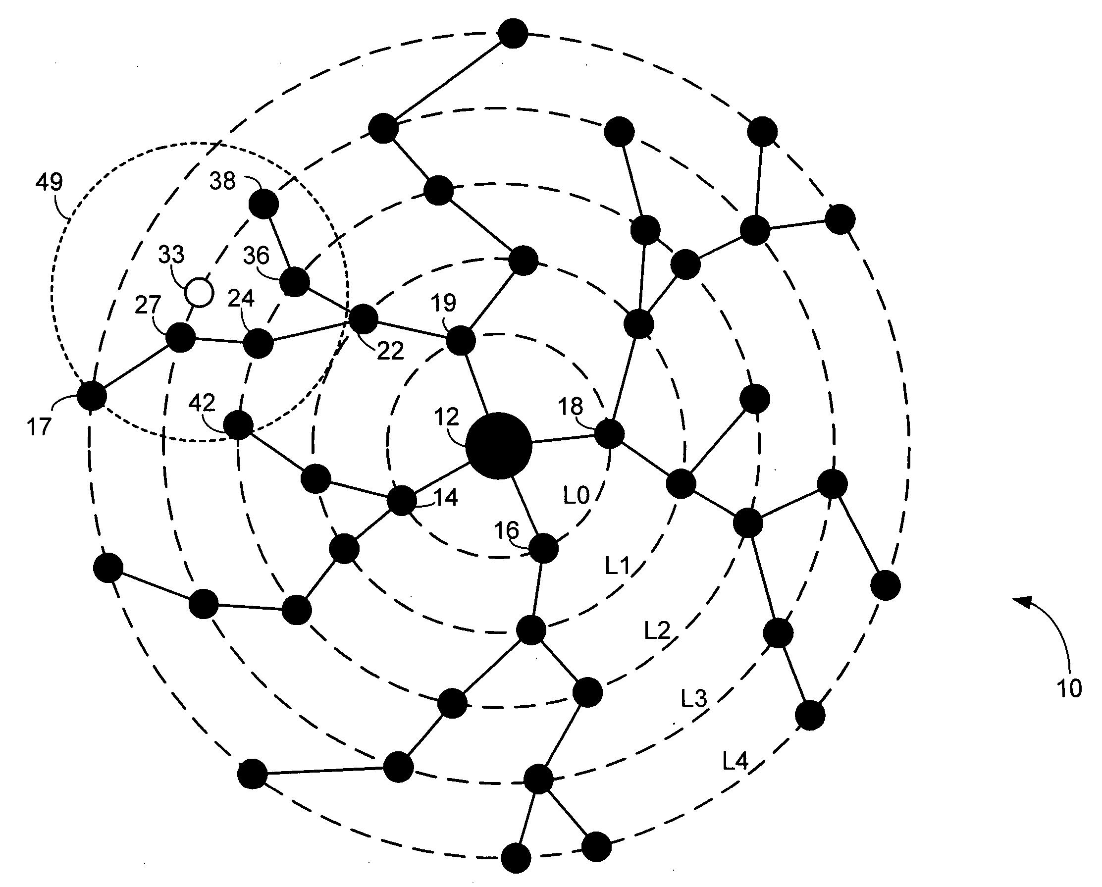
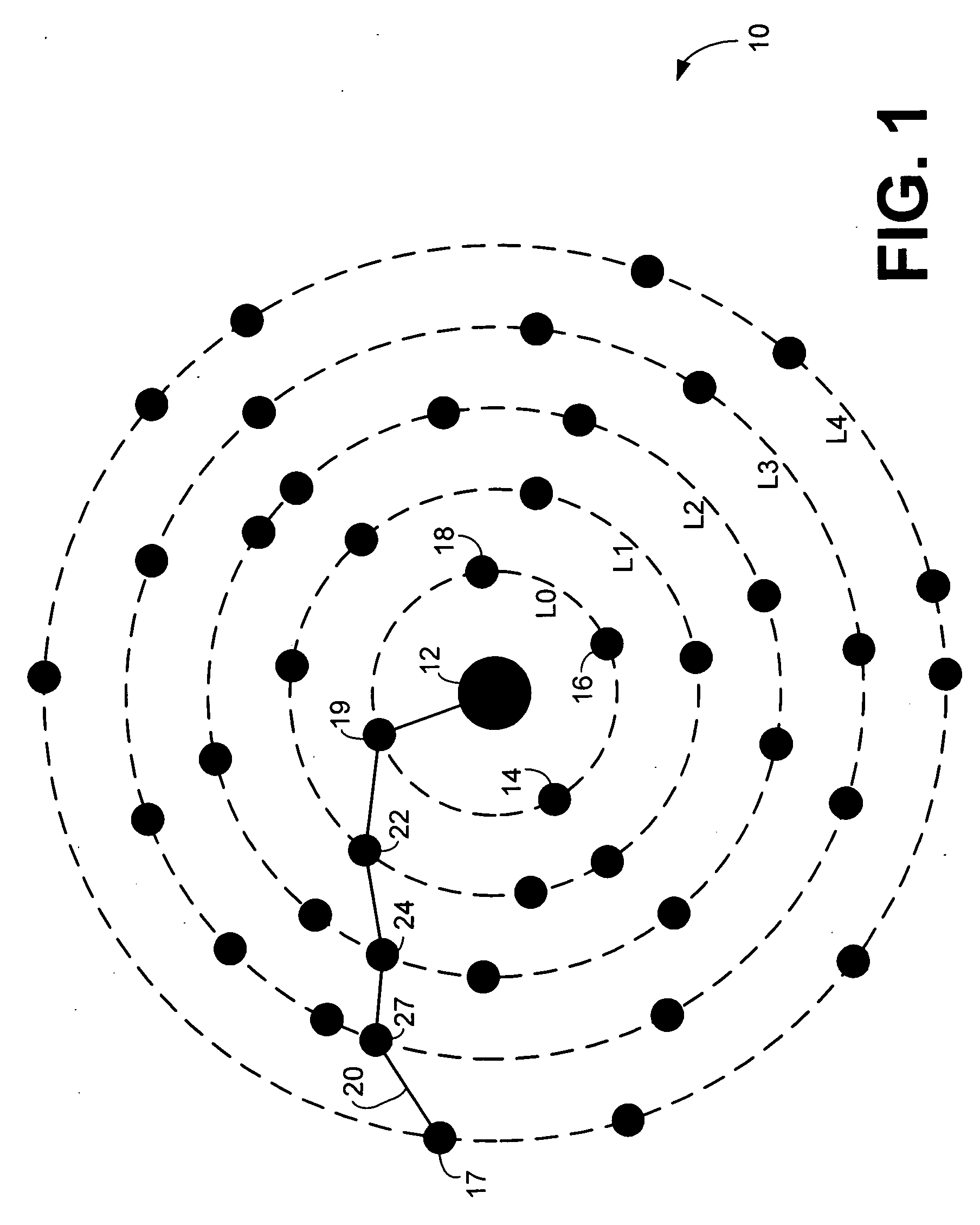
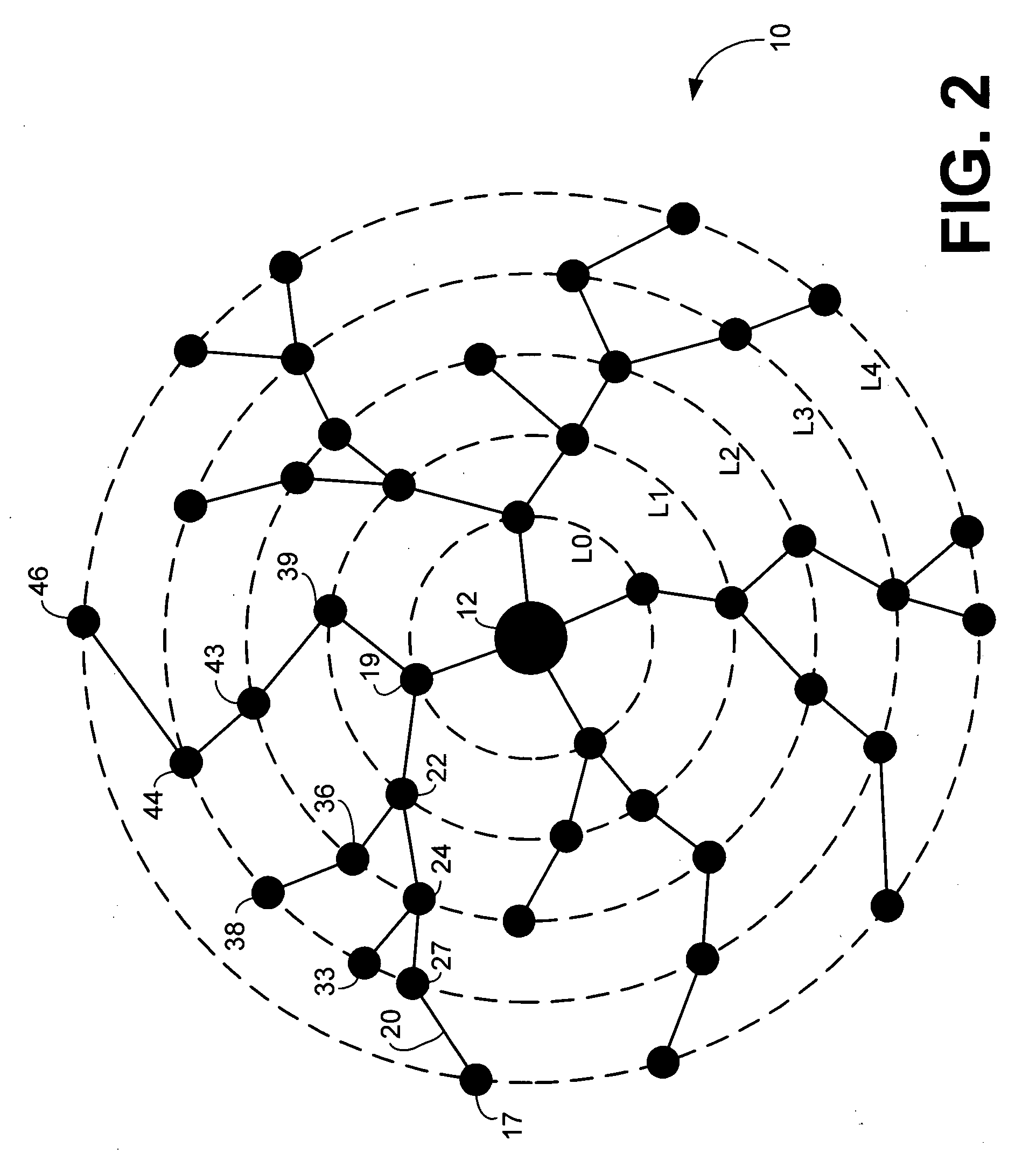
[0040] One or more electronic signs each coupled to a transceiver or radio node that is communicably coupled to an access node may change its display, as directed by the access node. The access node is configured to receive data related to adjusting information displayed on one or more of the electronic signs. The access node wirelessly transmits an outbound communication to a number of radio nodes logically distributed around the access node. One or more of the radio nodes may be configured without an electronic sign and, instead, be co...


PUM


Abstract

One or more electronic signs each coupled to a transceiver or radio node that is communicably coupled to an access node may change its display, as directed by the access node. The access node is configured to receive data related to adjusting information displayed on one or more of the electronic signs. The access node wirelessly transmits an outbound communication to a number of radio nodes logically distributed around the access node. One or more of the radio nodes or may be configured without an electronic sign but instead be configured to repeat the outbound communication. A recipient radio node receives the outbound communication message and executes instructions contained in the outbound communication message so that its electronic sign changes the display of information, such as the price.

Description

CROSS REFERENCE TO RELATED APPLICATION [0001] This application is a continuation-in-part of the copending U.S. utility application entitled, “System and Method for a Wireless Mesh Network,” having Ser. No. 10 / 938,263, filed Sep. 10, 2004, which is entirely incorporated herein by reference.FIELD OF THE INVENTION [0002] This invention generally pertains to wireless communications and, more particularly, to a system, method, and apparatus for meshing a network of wireless signs and informational displays. BACKGROUND OF THE INVENTION [0003] The monitoring and controlling of devices located remotely from a central location has historically provided many challenges. The ability to detect a condition at a remotely located position or to exercise control over a system (such as turning a device off and on or otherwise causing a changed condition) from a central location has oftentimes been limited by the distance of the central control location from the device that is monitored or controlled...

Claims


Application Information

Patent Timeline
Patent Type & Authority Applications(United States)
IPC IPC(8): H04Q7/24H04W40/00H04W52/04H04W52/46H04W84/18H04W88/04
CPCG06F3/147G09G2370/16G09G2380/04G09G2380/06H04B7/026H04W88/04H04W4/12H04W40/00H04W52/04H04W52/46H04W84/18H04B7/2606
Inventor RATIU, OVIDIUCHILOM, MARIUS OVIDIUTICUS, ION
Owner NIVIS
Why Eureka
Try Eureka