Hand manipulated pusher apparatus with adjustably spaced teeth for cleaning uneven corrugated surfaces

a pusher and uneven technology, applied in the direction of cleaning equipment, carpet cleaners, cleaning apparatus and processes, etc., can solve the problems of insufficient standard shovels, difficult cleaning of corrugated floor surfaces of refrigerated bodies, and production of bottom layer to be crushed on the corrugated floor

Inactive Publication Date: 2006-03-23
KUHNS MARK J +1
View PDF12 Cites 12 Cited by
  • Summary
  • Abstract
  • Description
  • Claims
  • Application Information

AI Technical Summary

Benefits of technology

[0015] The pusher blade may be curved to provide a concave front to allow for the collection of debris from the flooring to be accumulated and pushed out of the rear of the trailer or container. Additionally, the sides of the blade may have frontwardly extending perpendicular sidewalls to retain the debris on the pusher blade instead of allowing excess debris to be pushed off and around the sides thereof. Such sidewalls on the pusher blade may also be used to clear debris from against the sidewalls of the trailer.

Problems solved by technology

Often, in a truckload of perishable food or produce, the weight combined with the shifting around of the cargo during transport will cause some of the produce on the bottom layer to be crushed on the corrugated floor, both on top of and in the recessed channels.
Corrugated floor surfaces of refrigerated bodies are difficult to clean, particularly when the channels become encrusted or caked with mash and ice.
Standard shovels are inadequate for the task because the shovel blade cannot clean inside the recessed channels.
Implements such as rakes or ice chippers having a plurality of fixed, regularly spaced teeth or tines are also not suitable because in most instances the teeth will not fit into the recessed channels or corrugations.
The distance between channels of a corrugation may vary considerably from one container to another, and from one manufacturer to another, because of the lack of manufacturing standards for such flooring.
Single tined implements have been partially effective in cleaning corrugated surfaces, but the process of cleaning each recessed channel or corrugation individually is excessively time consuming.
Moreover, there is a tendency for debris removed from one channel to fall into an adjacent, previously cleaned channel.
Shortcomings of the Murphy device render it unable to clean a large percentage of the corrugated floors for which it is intended to be used.
One problem with the Murphy device is that equidistantly spaced teeth, a central feature of the disclosed device, cannot accommodate a floor with non-uniformly spaced corrugations, as occurs at a joint between floor segments or near a wall.
Another problem is that the teeth are all of equal vertical depth and therefore the device cannot be used to simultaneously clean channels of varying depths or sections of corrugated flooring having a combination of channels and flat surfaces such as may exist adjacent to a wall of the container.
An additional problem is that if the device is used to clean the debris of fungible goods and not just ice, the springs may tend to become caked with debris resulting in the misalignment of teeth at the bottom of the pusher blade.
A further problem is that the squared-off distal ends of the teeth will not be capable of cleaning to the bottom of the channels (or of cleaning both the bottoms and the sides of the channels) of most modern corrugated flooring which typically have channels that narrow or taper inwardly towards the respective bottoms.

Method used


Image

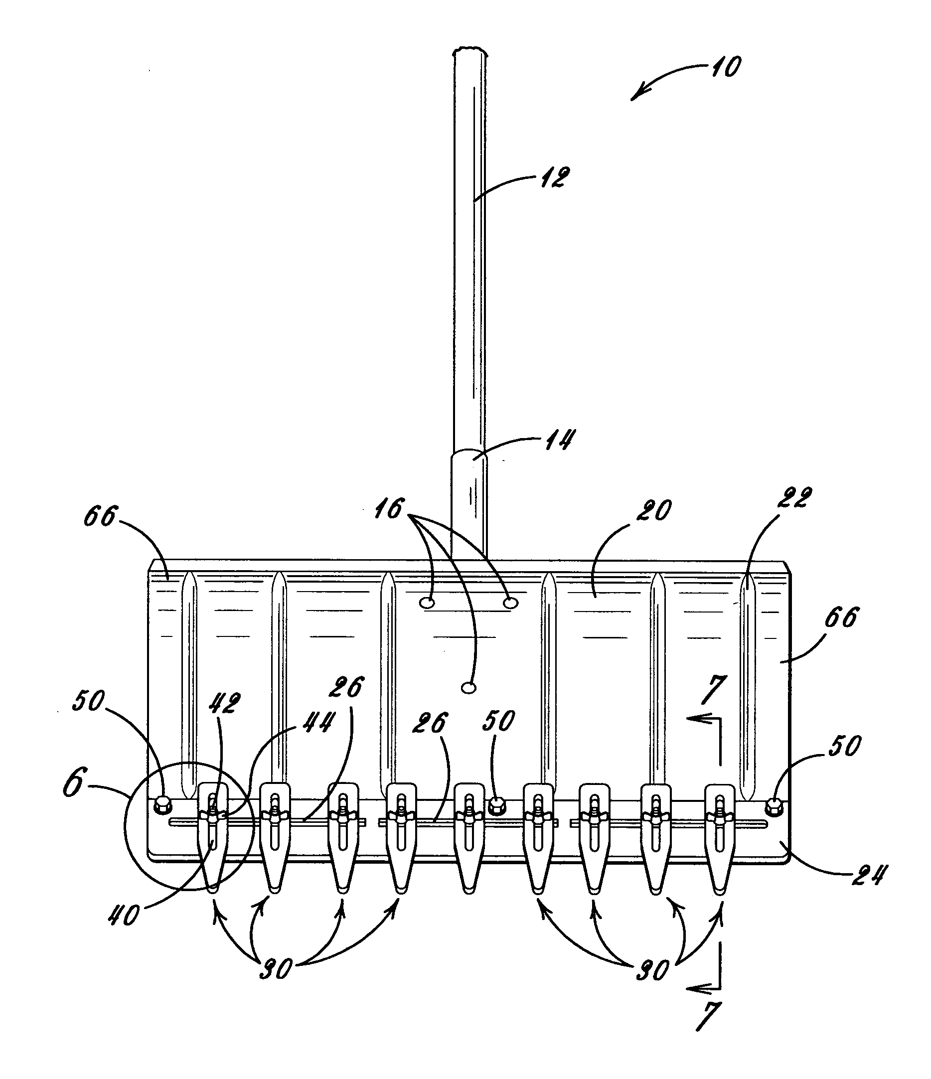
  • Hand manipulated pusher apparatus with adjustably spaced teeth for cleaning uneven corrugated surfaces
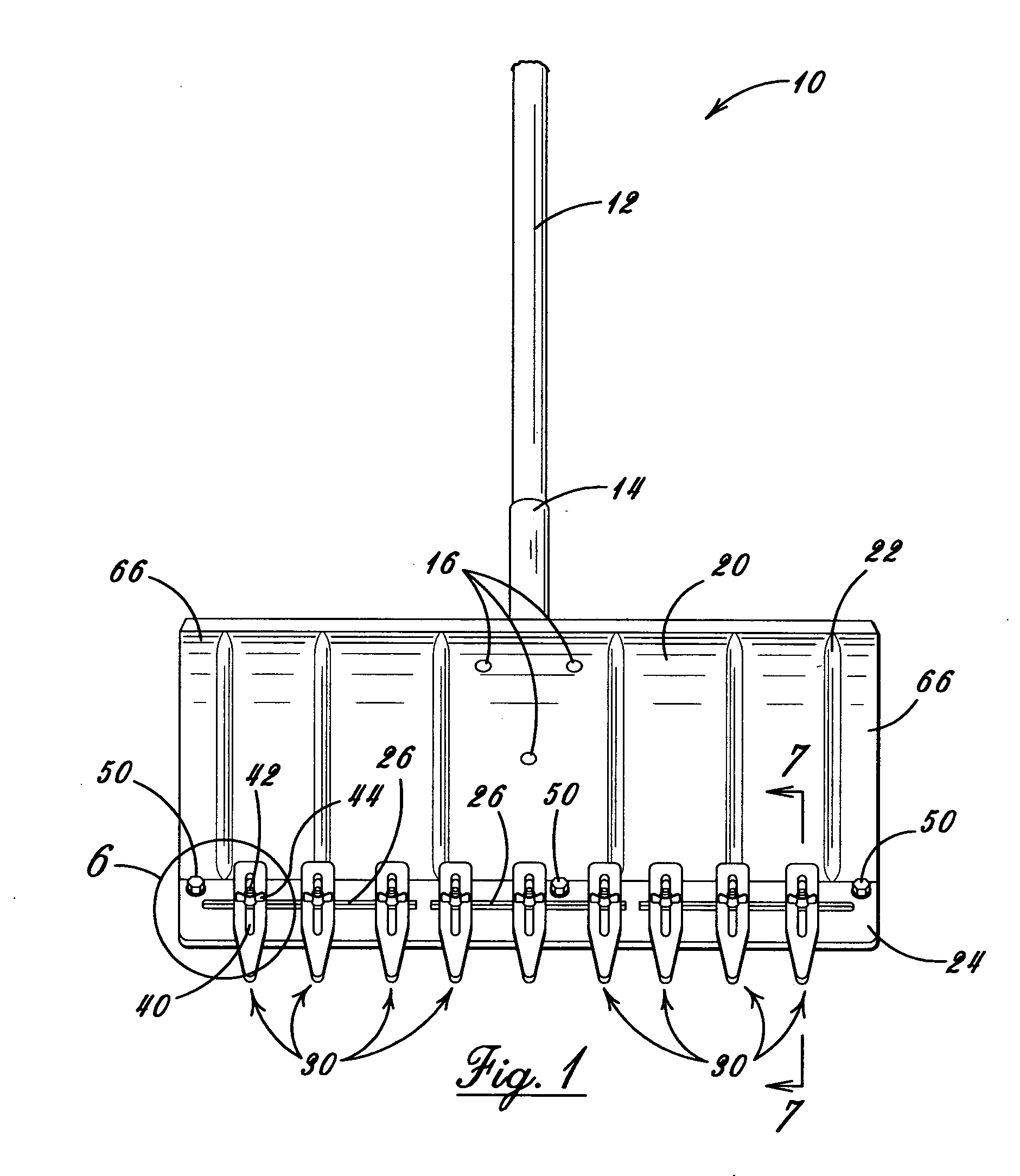
  • Hand manipulated pusher apparatus with adjustably spaced teeth for cleaning uneven corrugated surfaces
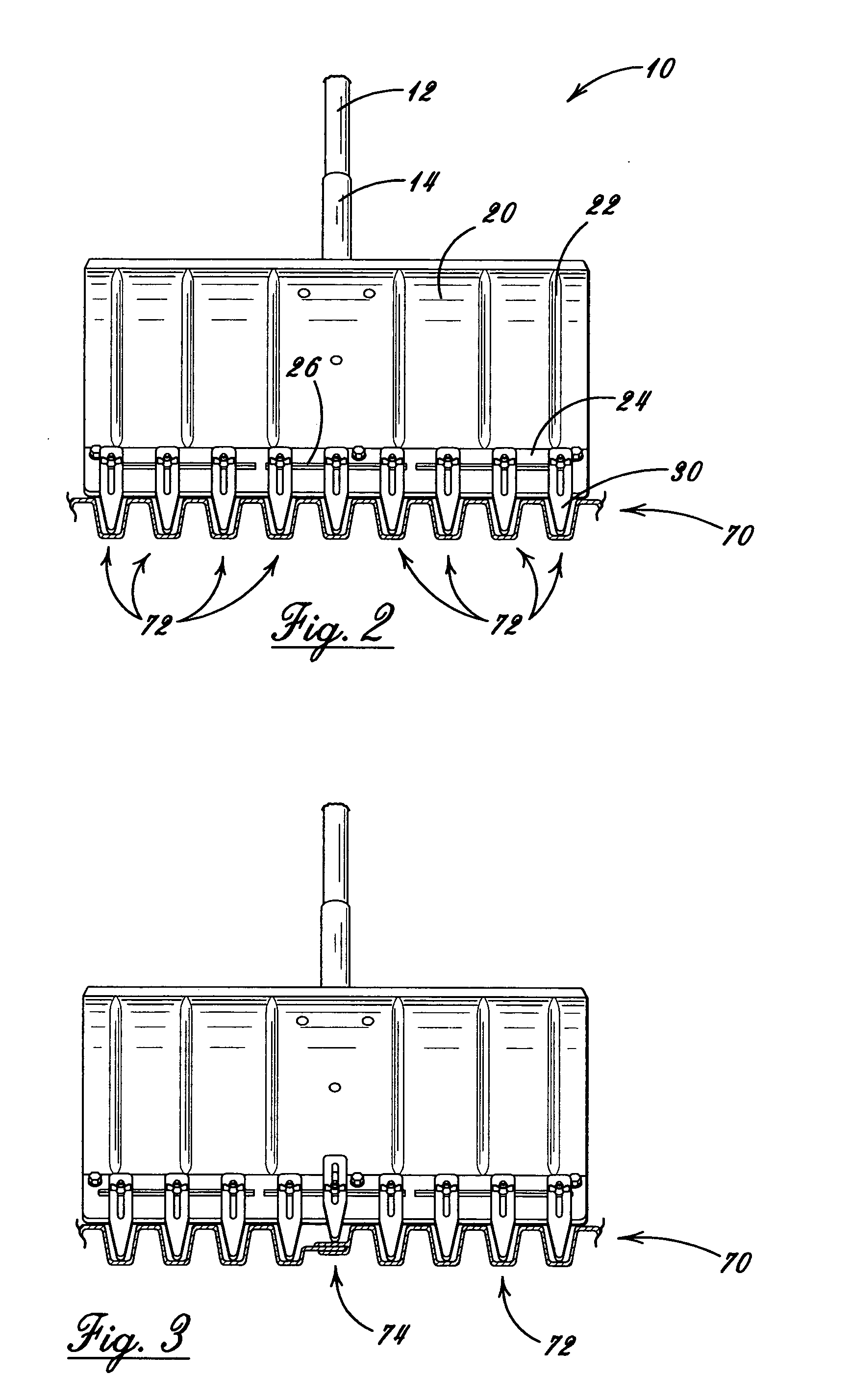
  • Hand manipulated pusher apparatus with adjustably spaced teeth for cleaning uneven corrugated surfaces

Examples


Embodiment Construction

[0024] The following detailed description is of the best presently contemplated mode of carrying out the invention. The description is not intended in a limiting sense, and is made solely for the purpose of illustrating the general principles of the invention. The various features and advantages of the present invention may be more readily understood with reference to the following detailed description taken in conjunction with the accompanying drawings.

[0025] Referring now to the drawings in detail, where like numerals refer to like parts or elements, there is shown in FIG. 1 a front plan view of the pusher apparatus 10 of the present invention. The pusher apparatus 10 comprises a handle 12, a blade 20, and an edge plate 24 onto which a plurality of laterally and vertically adjustable teeth 30 are arrayed.

[0026] The pusher blade 20 is an essentially planar element, generally rectangular in shape and is preferably formed from a strong material such as galvanized sheet steel, a sui...


PUM


Abstract

A manually manipulated shovel-like device for cleaning corrugated floors along the bottom of refrigerated containers and trailers having a blade, an elongate handle extending from the proximal end of the blade, and a plurality of elongate cleaning teeth extending perpendicularly from the opposed distal end of the blade, each of the cleaning teeth being individually slidably adjustable in both the lateral and the vertical directions with respect to the distal edge of the blade to enable the device to clean corrugated floors having unequally spaced apart corrugations of varying depth, joints between sections of corrugated panels, and uncorrugated sections near walls of the container, each of said teeth additionally being individually removable and replaceable from the blade so that teeth of various geometrical configurations and functional features may be used, including teeth tapered to a narrower distal tip, teeth of generally uniform width, and teeth having chisel-pointed edges, the blade optionally being curved to have a concave front side, the blade further optionally having frontwardly extending sidewalls.

Description

BACKGROUND OF THE INVENTION [0001] The present invention relates generally to the field of manually manipulated cleaning devices for the specific use of cleaning the channels or recessed corrugations in uneven corrugated floors along the bottom of refrigerated trailers, vans, and containers. More particularly, the present invention relates to an apparatus for cleaning the plurality of channels in a corrugated floor of a refrigerated trailer having a handle, a pusher blade, and a plurality of laterally and vertically adjustable teeth or fingers arrayed along the bottom edge of the pusher blade. [0002] The transportation of perishable commodities, produce, and foodstuffs in insulated refrigerated bodies such as trucks, trailers, and containers is prevalent around the world. The floors of these bodies are typically corrugated both to enhance the strength of the flooring to be able to support heavy loads of goods, as well as loading and unloading equipment, and to enable the circulation...

Claims


Application Information

Patent Timeline
Patent Type & Authority Applications(United States)
IPC IPC(8): E04F21/00
CPCB08B1/008A47L13/08
Inventor KUHNS, MARK J.PETERS, LYNN
Owner KUHNS MARK J
Why Eureka
Try Eureka