Lubricant gun

a lubricant gun and lubricant technology, applied in the direction of lubrication elements, manual lubrication, conduits/junctions, etc., can solve the problems of affecting the discharging of lubricant, idle operation of the lubricant gun,

Inactive Publication Date: 2006-03-23
TECHWAY INDAL
View PDF12 Cites 27 Cited by
  • Summary
  • Abstract
  • Description
  • Claims
  • Application Information

AI Technical Summary

Problems solved by technology

Therefore, the bubbles in the slide channel 102 and the lubricant supply hole 104 will cause idl

Method used


Image

  • Lubricant gun
  • Lubricant gun
  • Lubricant gun

Examples


Embodiment Construction

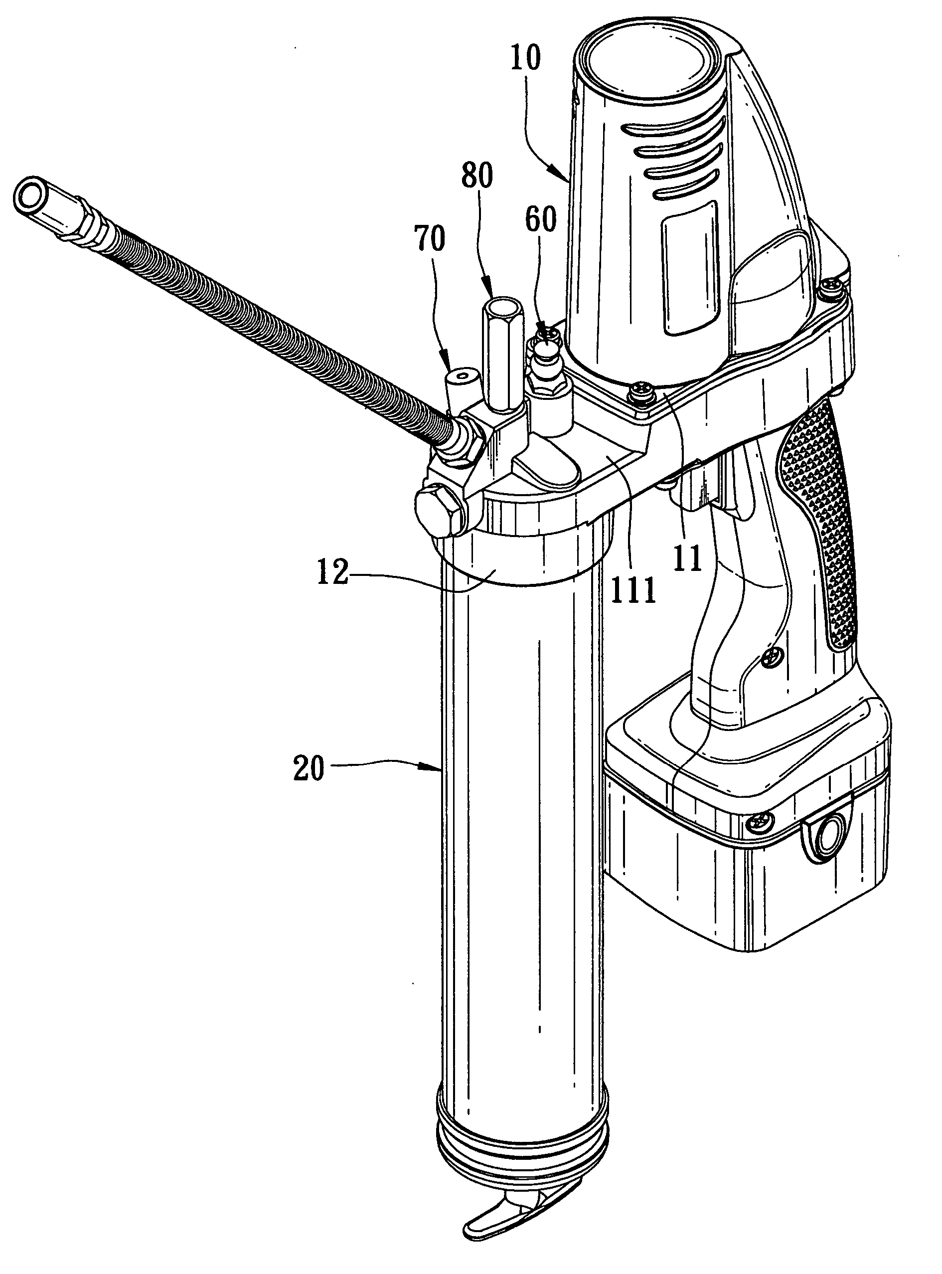
[0020] Referring to FIGS. 5, 6, and 7, the preferred embodiment of a lubricant gun according to this invention is shown to include a housing 10, a lubricant reservoir 20, a motor 30, a power transmission 40, a plunger 50, an exhaust valve 60, a lubricant inlet 70, and a safety valve 80.

[0021] The housing 10 includes a gun compartment 11 having a front portion 111 and a surrounding wall 12 at a bottom of the front portion 111, a discharge spout 13 mounted on the front portion 111, a slide channel 14 extending in the front portion 111 along a longitudinal direction (x) and fluidly communicated with the discharge spout 13, a lubricant supply passage 15 defined by the front portion 111 and the surrounding wall 12 and having a lubricant supply hole 16 fluidly connected to the slide channel 14 in a transverse direction (y) transverse, or preferably perpendicular, to the longitudinal direction (x), and a gas-discharging hole 17 fluidly communicated with the slide channel 14 in the transve...


PUM


Abstract

A lubricant gun includes a housing, a lubricant reservoir, a plunger, and an exhaust valve. The housing includes a discharge spout, a slide channel fluidly communicated with the discharge spout, a lubricant supply passage having a lubricant supply hole fluidly connected to the slide channel, and a gas-discharging hole fluidly communicated with the slide channel. The lubricant reservoir is connected to the housing and is fluidly communicated with the slide channel through the lubricant supply passage and the lubricant supply hole. The plunger has a pushing portion received in the slide channel for sliding reciprocatingly therein. The exhaust valve is mounted on the housing and is fluidly communicated with the gas-discharging hole.

Description

CROSS-REFERENCE TO RELATED APPLICATION [0001] This application claims priority of Taiwanese application No. 093128842, filed on Sep. 23, 2004. BACKGROUND OF THE INVENTION [0002] 1. Field of the Invention [0003] The invention relates to a lubricant gun, more particularly to a lubricant gun capable of discharging gas effectively. [0004] 2. Description of the Related Art [0005] Referring to FIGS. 1, 2 and 3, a conventional battery-operated lubricant gun includes a housing 1, a lubricant reservoir 2, an electric motor 3, a power transmission 4, a plunger 5, and an exhaust valve 6. The housing 1 has a discharge spout 101, a slide channel 102 extending along an axial direction and fluidly communicated with the discharge spout 101, a lubricant supply passage 103 fluidly communicated with the slide channel 102, a lubricant supply hole 104 fluidly connected to the lubricant supply passage 103 and the slide channel 102, and a gas-discharging hole 105. The lubricant reservoir 2 is connected to...

Claims


Application Information

Patent Timeline
IPC IPC(8): F16N21/00
CPCF16N3/12F16N3/08
Inventor CHEN, LI-CHI
Owner TECHWAY INDAL
Why Eureka
Try Eureka