Inkjet printer head and method of manufacturing the same

a printer head and printer head technology, applied in printing and other directions, can solve the problems of large power consumption, inability to fully integrate the nozzle, and inability to achieve high-efficiency nozzles, and achieve the effect of improving ink ejection performan

Inactive Publication Date: 2006-03-23
SAMSUNG ELECTRONICS CO LTD
View PDF0 Cites 21 Cited by
  • Summary
  • Abstract
  • Description
  • Claims
  • Application Information

AI Technical Summary

Benefits of technology

[0010] The present general inventive concept provides an inkjet printer head capable of improving ink eje

Problems solved by technology

However, since all the bubbles are generated by a single surface of the heater (i.e., in only one direction), ink ejection performance of the heater has inherent limitations.
In this case, however, high inte

Method used


Image

  • Inkjet printer head and method of manufacturing the same
  • Inkjet printer head and method of manufacturing the same
  • Inkjet printer head and method of manufacturing the same

Examples


Embodiment Construction

[0050] Reference will now be made in detail to the embodiments of the present general inventive concept, examples of which are illustrated in the accompanying drawings, wherein like reference numerals refer to the like elements throughout. The embodiments are described below in order to explain the present general inventive concept by referring to the figures.

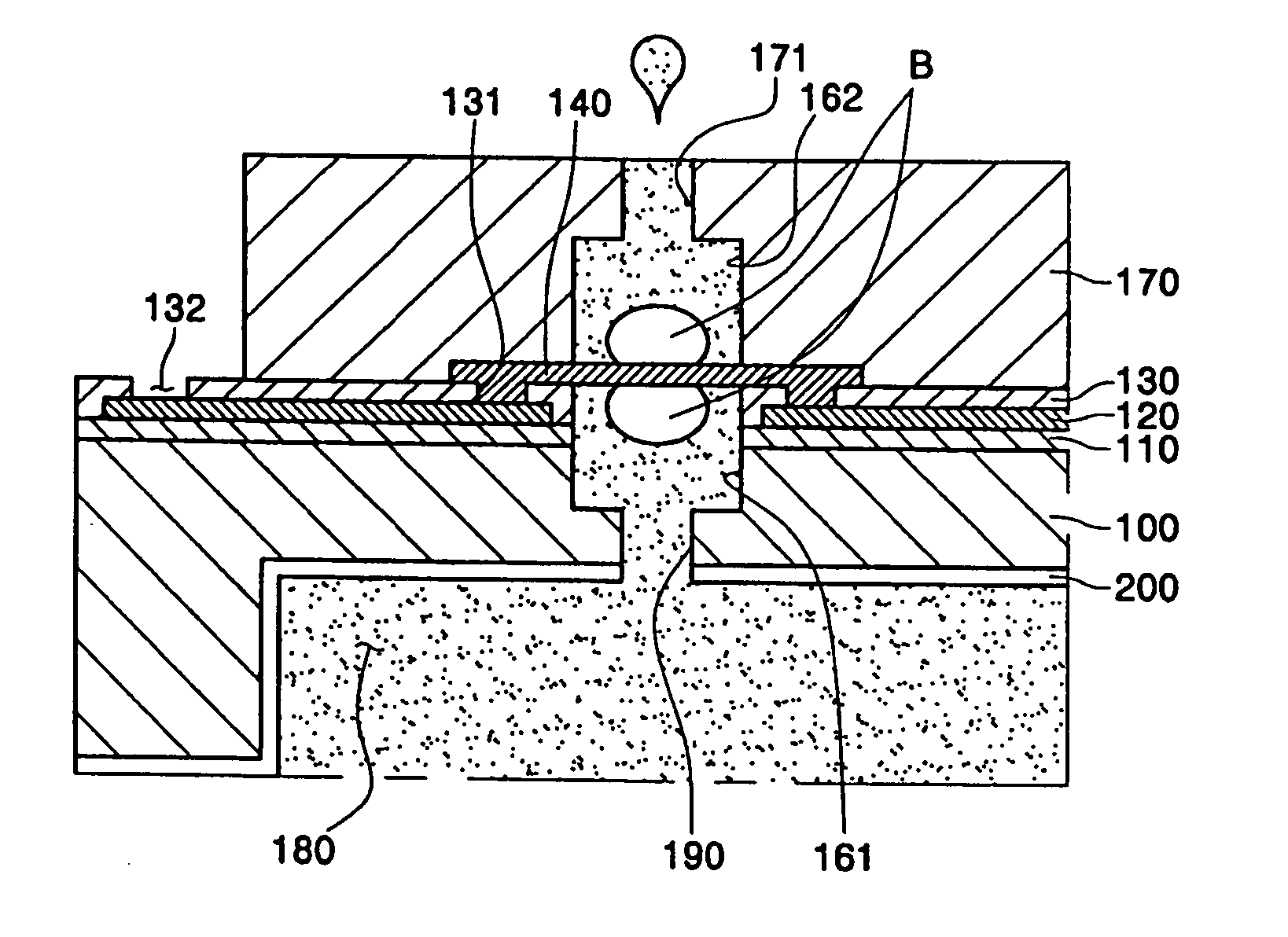
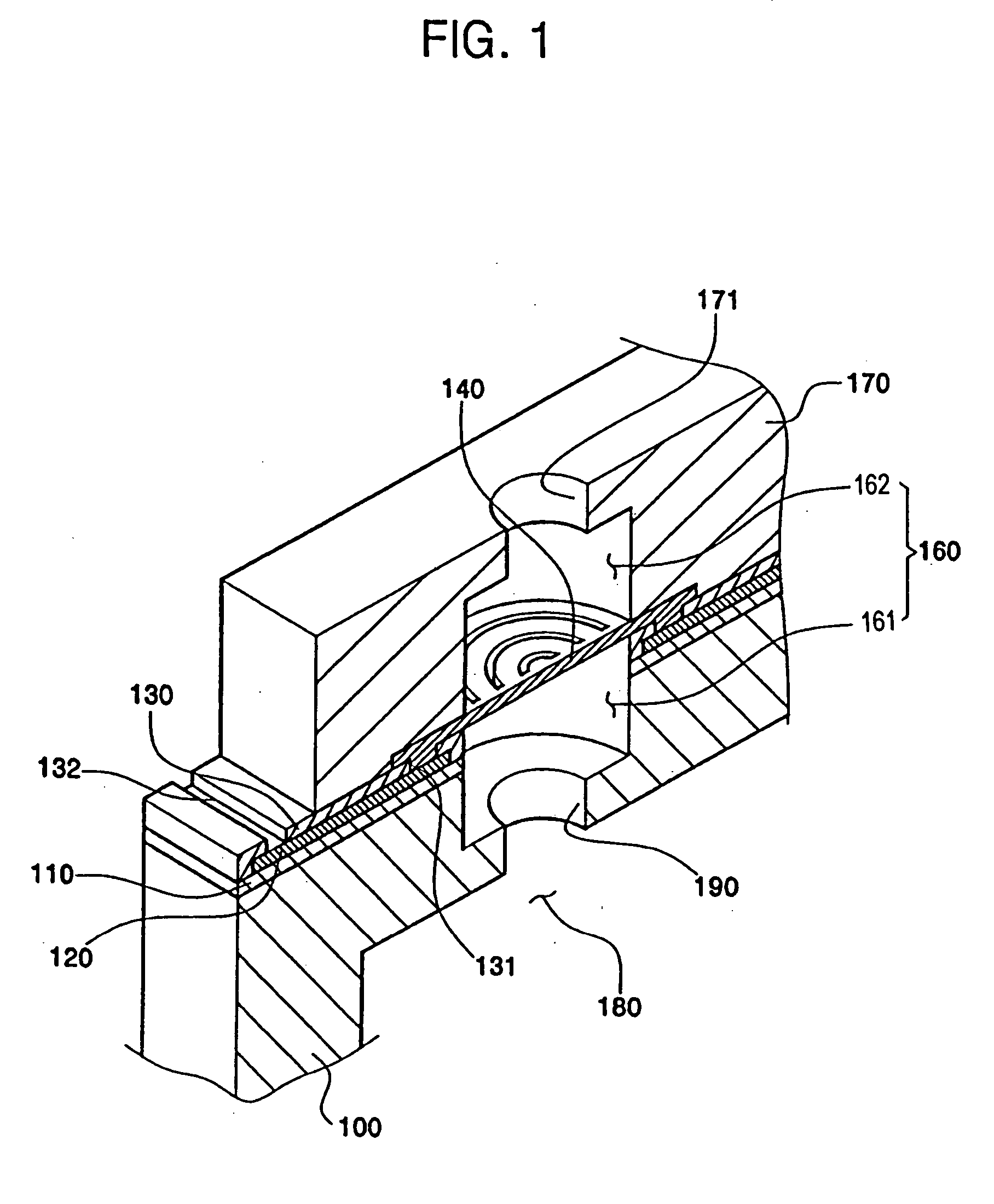
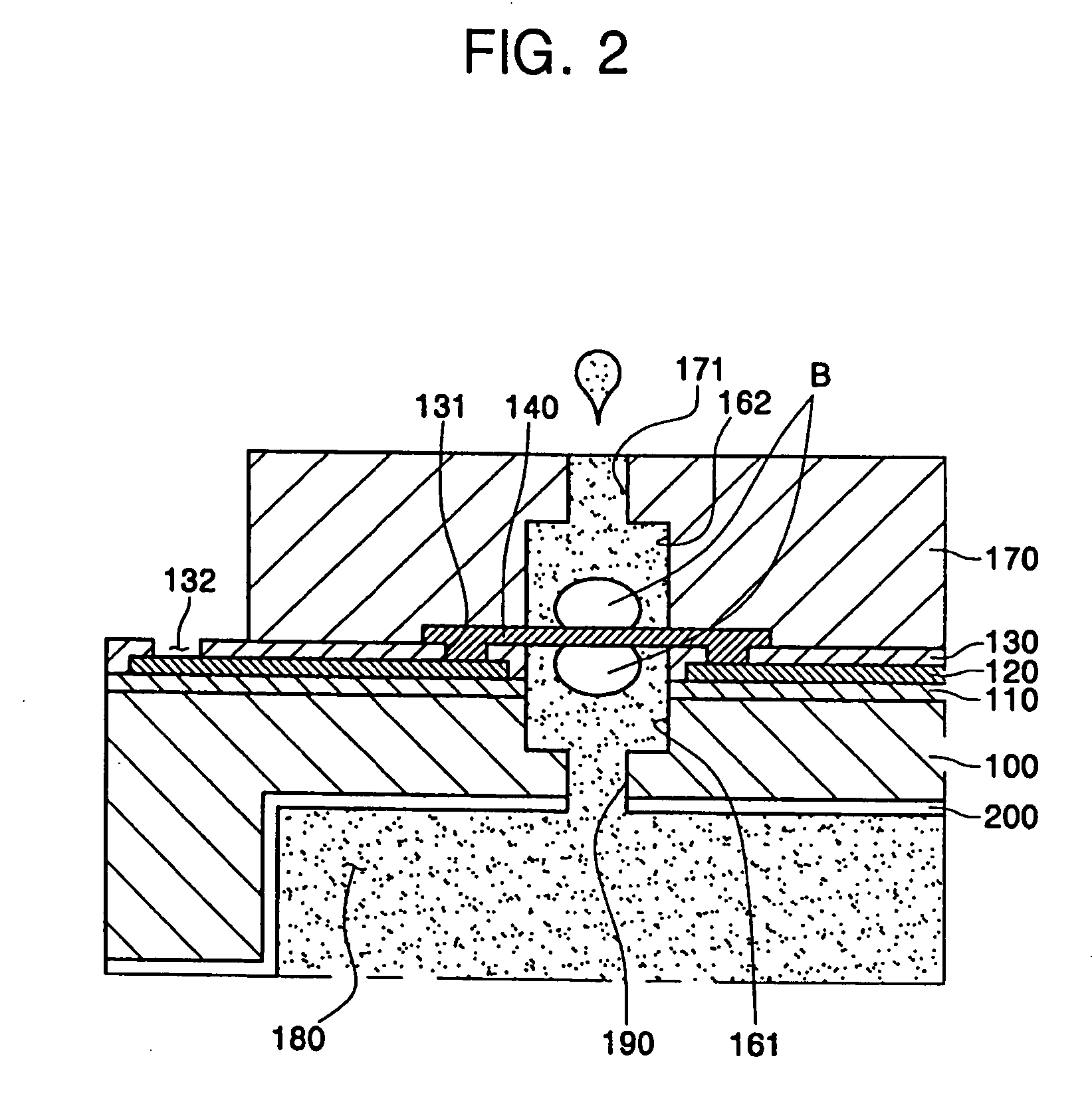
[0051] As illustrated in FIGS. 1 and 2, an inkjet printer head is provided with a manifold 180 formed at a rear surface of a substrate 100 in order to supply ink from an ink container (not shown) attached thereto. The substrate 100 may be a wafer used to manufacture a semiconductor integrated circuit. In addition, the manifold 180 is in fluid communication with the ink container (not shown), and an ink channel 190 is formed on the manifold 180 to extend through the substrate 100.

[0052] The ink channel 190 controls an ink ejection amount from the inkjet printer head and should be precisely formed in order to implement fine ima...


PUM


Abstract

An inkjet printer head includes a substrate having a manifold and an ink channel to supply ink, a nozzle plate formed on the substrate, a chamber formed between the substrate and the nozzle plate and extending toward the substrate and the nozzle plate, an electrode formed at an interface between the substrate and the nozzle plate and around the chamber, and a heater having both ends extending in contact with the electrode to be suspended on the chamber in direct contact with the ink and to generate bubbles from both surfaces thereof. The inkjet printer head is capable of improving manufacturing process efficiency by omitting a process of separately forming a heater passivation layer, operating the heater at low electric power by omitting the heater passivation layer, improving integrity of a nozzle by lowering a working voltage, and improving reliability in manufacturing processes by locating the suspended heater to be in parallel with the substrate and the electrode.

Description

CROSS-REFERENCE TO RELATED APPLICATIONS [0001] This application claims the benefit of Korean Patent Application No. 2004-74731, filed Sep. 17, 2004, the disclosure of which is hereby incorporated herein by reference in its entirety. BACKGROUND OF THE INVENTION [0002] 1. Field of the Invention [0003] The present general inventive concept relates to an inkjet printer head and a method of manufacturing the same, and more particularly, to an inkjet printer head to generate bubbles from upper and lower portions of a heater and a method of manufacturing the same. [0004] 2. Description of the Related Art [0005] Generally, an inkjet printer head prints images with predetermined colors by ejecting ink droplets to a desired position of a recording medium. The inkjet printer head may generally be classified into two categories depending on an ejection mechanism used to eject the ink droplets. The inkjet printer head may be a thermal driving type that uses a heat source to generate bubbles in t...

Claims


Application Information

Patent Timeline
IPC IPC(8): B41J2/05
CPCB41J2/1601B41J2/1628B41J2/1629B41J2/1646B41J2/1634B41J2/1639B41J2/1642B41J2/1631B41J2/05
Inventor PARK, SUNG-JOONKWON, MYONG-JONGKIM, KYONG-ILKIM, KWANG-RYULKIM, NAM-KYUNPARK, YONG-SHIKHAN, EUN-BONGHA, YOUNG-UNGMIN, JAE-SIKPARK, BYUNG-HA
Owner SAMSUNG ELECTRONICS CO LTD
Why Eureka
Try Eureka