Navigation and visualization of an access needle system

a technology which is applied in the field of navigation and visualization of access needles and stylets, can solve the problems of increasing patient recovery time after a procedure, requiring larger incisions in open surgery, and surgeons being forced to maneuver

Inactive Publication Date: 2006-03-23
GENERAL ELECTRIC CO
View PDF27 Cites 45 Cited by
  • Summary
  • Abstract
  • Description
  • Claims
  • Application Information

AI Technical Summary

Benefits of technology

[0007] A surgeon and other medical personnel can view the images on the display and guide surgical instrument into position within the patient. The medical instrument can be guided inside a patient without continuously acquiring real time x-ray exposure.

Problems solved by technology

While a needle and stylet can be guided by line-of-sight techniques during open surgery, there are drawbacks to open surgery.
First, open surgery requires larger incisions and increases patient recovery time following a procedure.
Second, a surgeon may be forced to maneuver around various obstructions to maintain an unobstructed view.
Maneuvering around obstructions and changing positions can become cumbersome if a surgeon has to guide the needle and stylet to various locations along the patient's anatomy.
The difficulty of which can be multiplied two-fold if a surgeon desires to return the needle and stylet to a prior position and orientation.
For surgeons that have to routinely perform such procedures, the x-ray doses can become excessive and unhealthy.
Also, updating the x-ray images may require rotation of the C-arm during a procedure and require medical personnel to relocate or reposition during the imaging sequence risk contaminating the sterile field.

Method used


Image

  • Navigation and visualization of an access needle system
  • Navigation and visualization of an access needle system
  • Navigation and visualization of an access needle system

Examples


Embodiment Construction

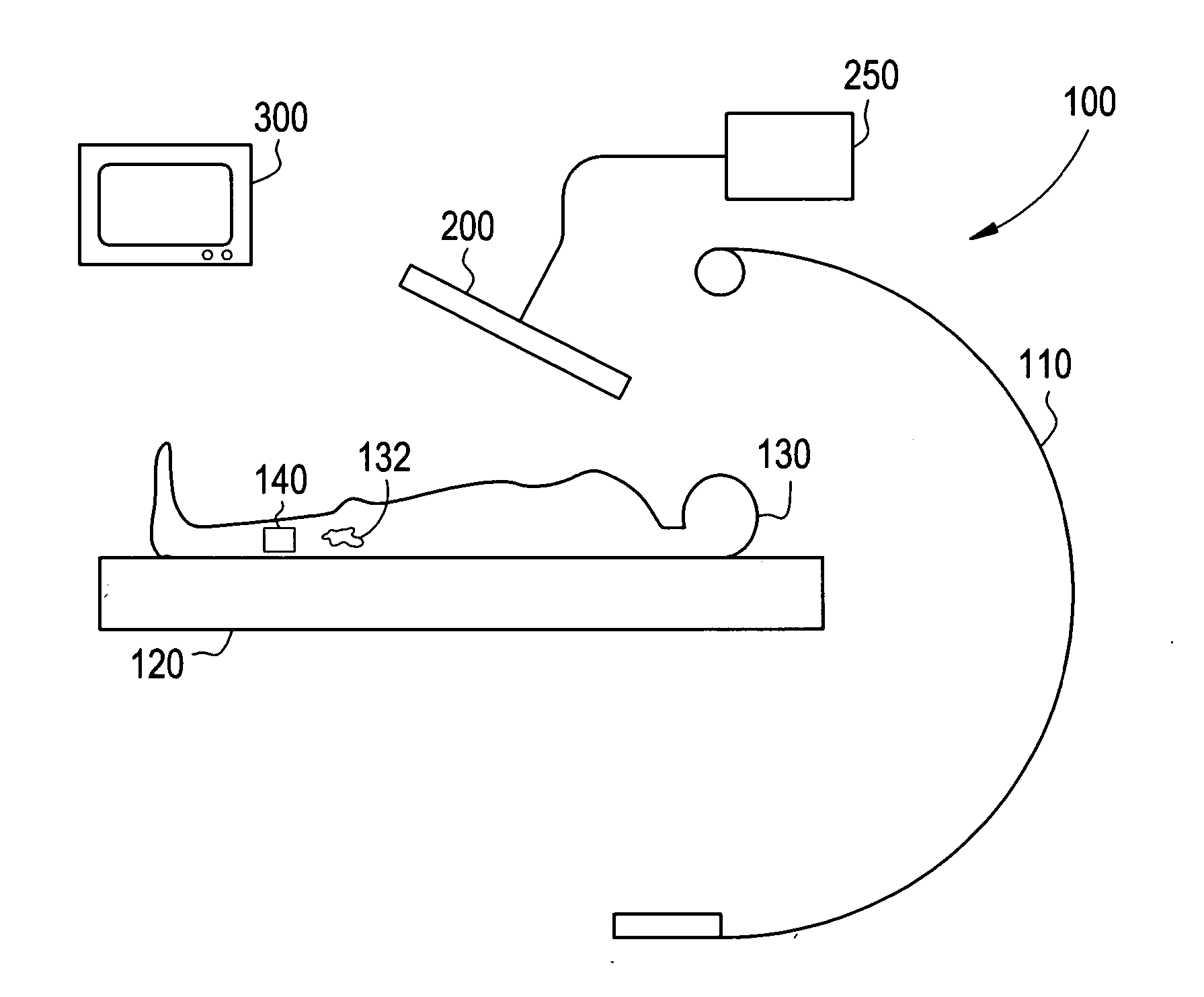
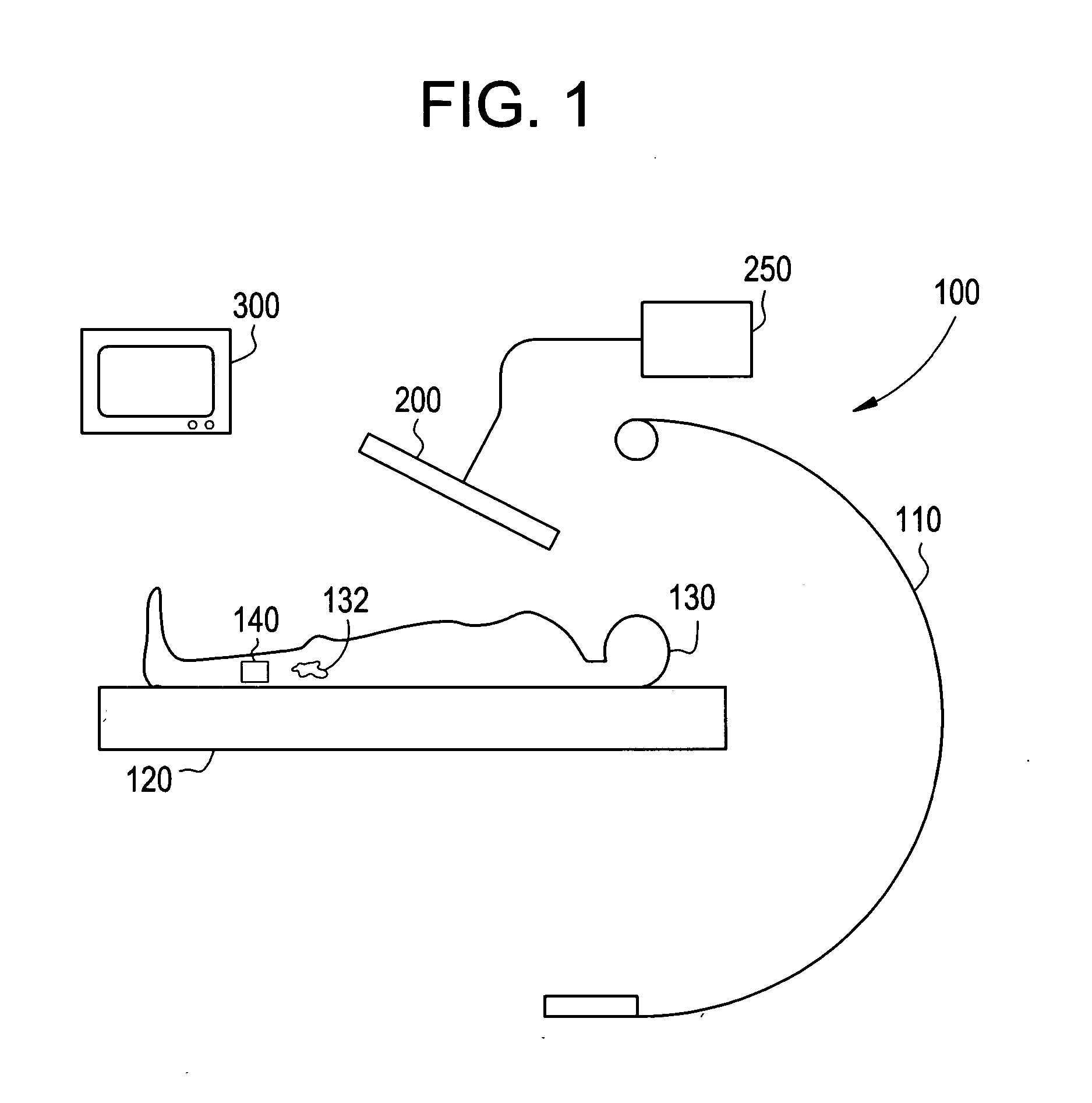
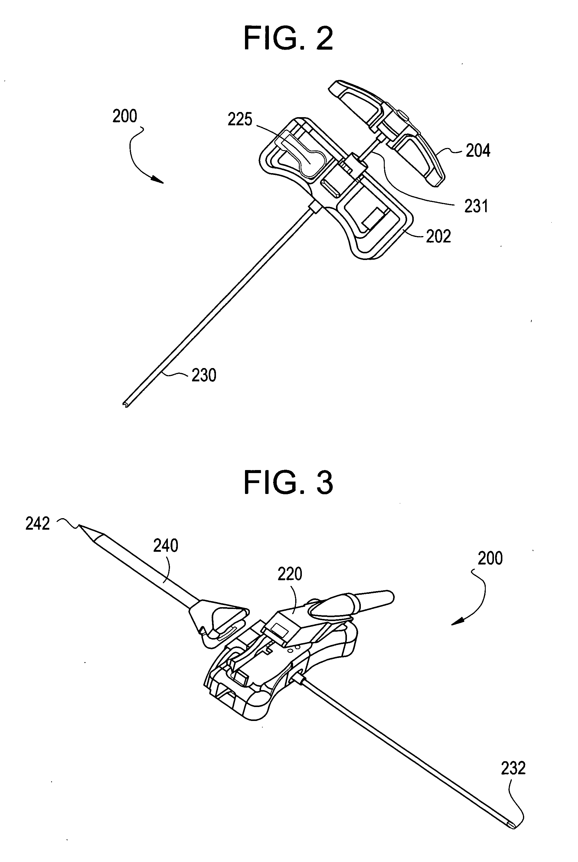
[0014]FIG. 1 illustrates a system 100 for navigating a surgical instrument during a procedure in accordance with an embodiment of the present invention. The system 100 includes an imaging device 110, a patient table 120, a patient 130, a region of interest 132, a transmitter 140, a surgical instrument 200, a monitor display 300, and a processing unit 250. The patient 130 is positioned on the surgical table 120 near an imaging device 120. The transmitter 140 is attached to the patient 130. The display 300 is positioned near the surgical table 120.

[0015] In operation, the imaging device 110 obtains x-ray images of the patient's bony anatomy. The x-ray images are transmitted to the processing unit 250. The transmitter 140 is attached to a portion of the patient's anatomy and transmits a signal. The signal is received by the surgical instrument 200. The surgical instrument 200 transmits data to the processing unit 250 that corresponds to the signal received from the transmitter 140. Th...


PUM


Abstract

A system for navigating and guiding a surgical instrument during a surgical procedure. A transmitter is positioned near a patient's anatomy. A receiver is attached to the surgical instrument. The position of the surgical instrument is tracked using the transmitter and receiver. A processing unit determines the location of the surgical instrument relative to the patient's anatomy and produces images with a pictorial representation of the surgical instrument and the patient's anatomy. The images are displayed on a display. A surgeon can view the images on the display and guide the surgical instrument into position inside the patient. The surgical instrument can be guided inside a patient without continuously producing real time x-ray exposures. Positions of the surgical instrument can be saved and displayed on the display along with the pictorial representation of the surgical instrument in its current position.

Description

BACKGROUND OF THE INVENTION [0001] The present invention generally relates to navigation and visualization of a needle and stylet system. In particular, the invention relates to a method and system for electromagnetically guiding a needle and stylet to a region of interest in a patient's anatomy. [0002] A needle and stylet combination may be used for performing various orthopedic and interventional procedures. For example, a needle and stylet may be used for procedures such as bone biopsies, guide wire placement, injections, and aspirations. Typically, the needle and stylet are guided to a region of interest in a patient's anatomy by either conducting open surgery and visually guiding the needle and stylet with line-of-sight techniques or by observing the manipulation of the needle and stylet in continuous real time x-ray images during the course of a procedure. [0003] While a needle and stylet can be guided by line-of-sight techniques during open surgery, there are drawbacks to ope...

Claims


Application Information

Patent Timeline
Patent Type & Authority Applications(United States)
IPC IPC(8): A61B5/05
CPCA61B6/12A61B5/06
Inventor VON JAKO, RONCORBETT, DAVID KEITHLEVINE, LEWIS J.ZASLAVSKY, ELLA
Owner GENERAL ELECTRIC CO
Why Eureka
Try Eureka