
Device and method for removing tooth applications such as brackets

a technology for brackets and teeth, applied in metal working devices, medical science, dentistry, etc., can solve the problems of pain for customers or patients, laborious debonding of such tooth applications, and thereby destruction of brackets

Inactive Publication Date: 2006-03-30
FERTON HLDG
View PDF13 Cites 8 Cited by
  • Summary
  • Abstract
  • Description
  • Claims
  • Application Information

AI Technical Summary

Benefits of technology

The invention provides a device for removing tooth applications that is painless, simple, and quick. The device uses a transmission element that receives an impulse and transmits it to the application, allowing for easy removal. The impulse conductor has an output surface that transmits the impulse to the application without causing any damage. The device can be adjusted to provide different frequencies and amplitudes of the impulse. The mass is accelerated to a pre-determinable impact velocity and then impacts the input surface of the impulse conductor. The impulse conductor is made of a hardened metal alloy and may have an intermediate element to dampen the impulse. The device may have a setting element to return the transmission element to the input surface after the impact of the mass. The device prevents the application from being involuntarily swallowed and can be used with different types of tooth applications.

Problems solved by technology

When removing the bracket, part of the adhering surface is lifted off the tooth face by compressing the outer parts with the pliers, but the bracket is thereby destroyed.
Due to the firm attachment to the tooth, debonding of such tooth applications is laborious and is often felt to be very painful by the customer or patient.
In addition, parts of the adamantine may also be removed, or dental crowns damaged.
Further, the back portions of the pharynx are difficult to access with the pliers, so that these methods can not be well used there.
A disadvantage of this technique is that heating of human tissue is always hazardous.
The known devices and methods allow only partial recycling of the brackets for further use due to the mechanical damage occurring during the removal.
Jewelry stones may also be damaged by removal, preventing re-use of the stones.

Method used


Image

  • Device and method for removing tooth applications such as brackets
  • Device and method for removing tooth applications such as brackets
  • Device and method for removing tooth applications such as brackets

Examples


Embodiment Construction

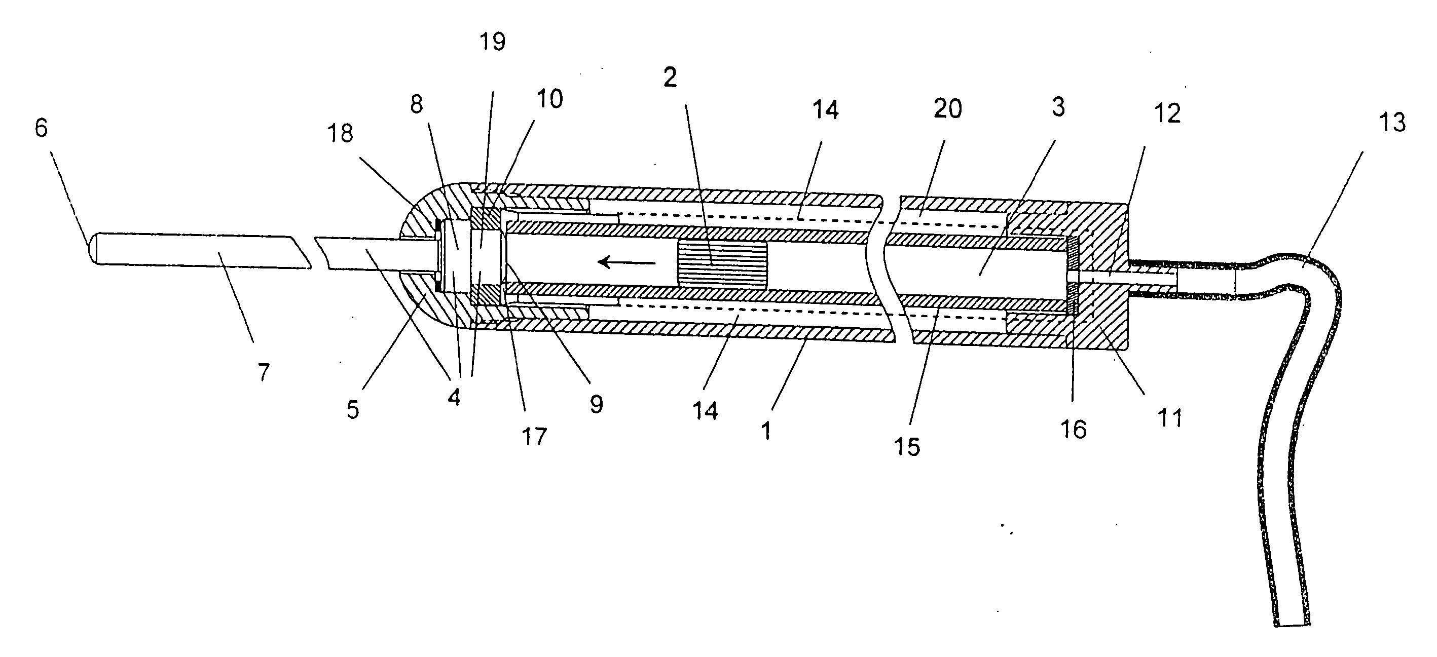
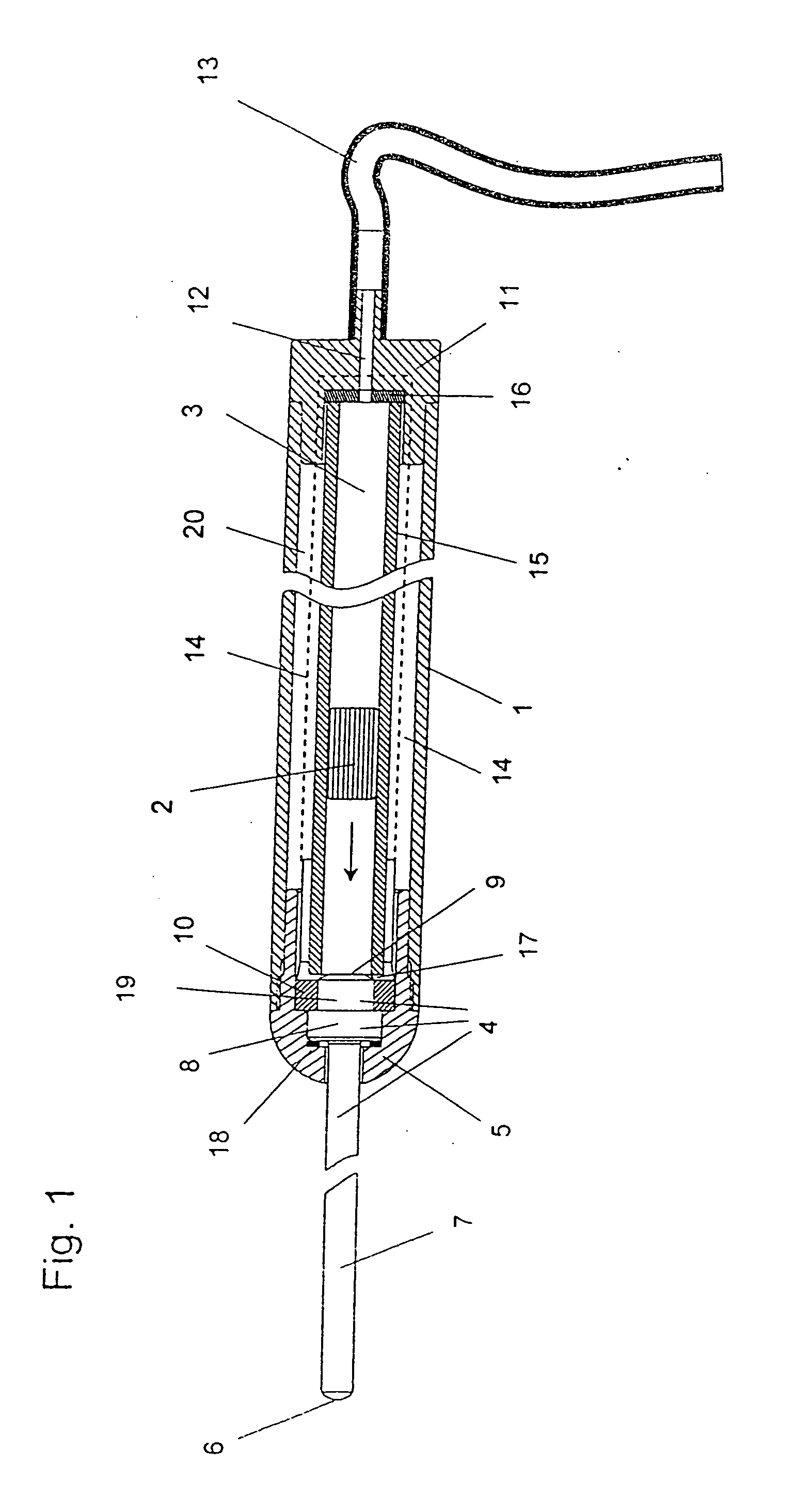
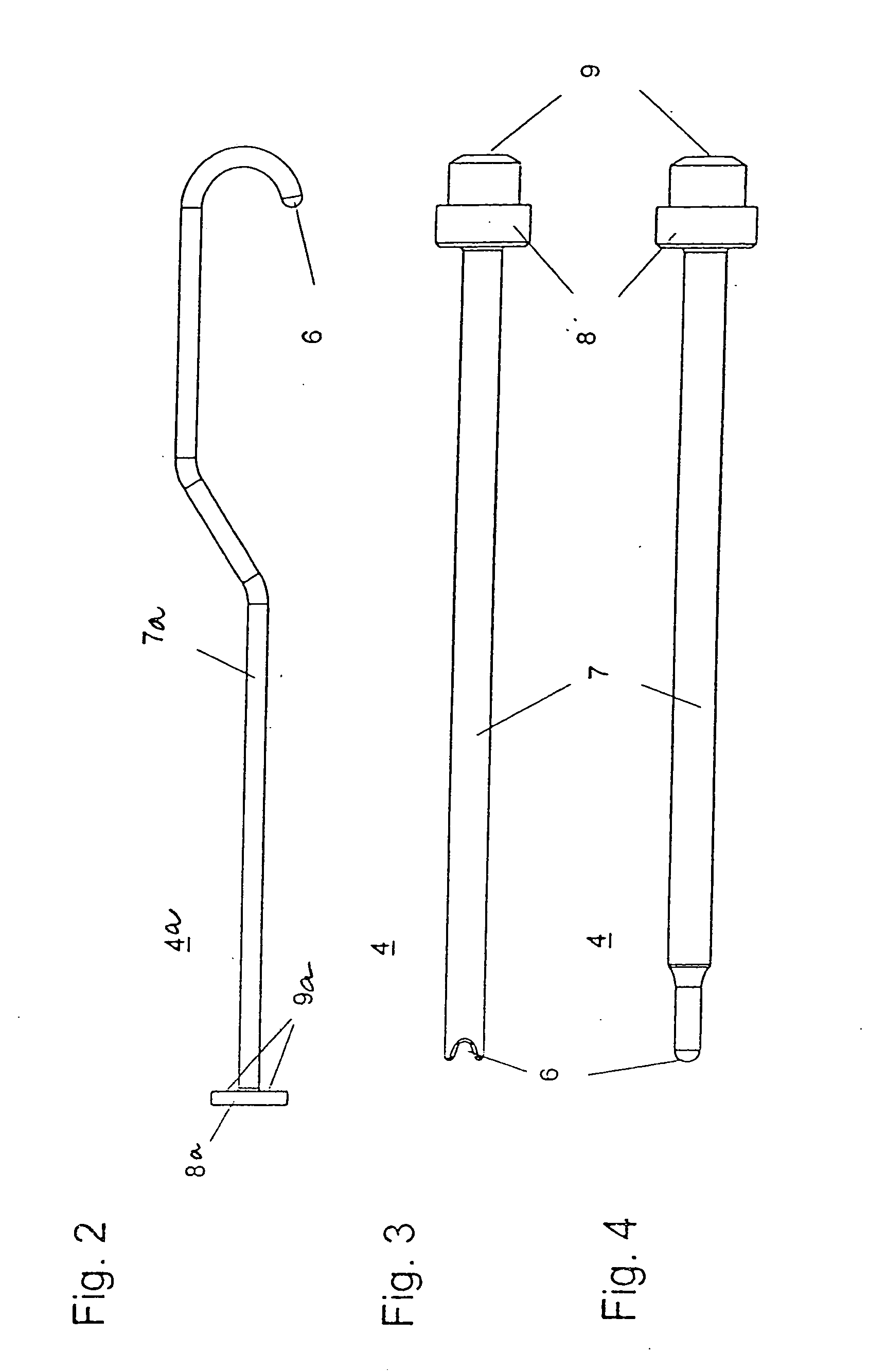
[0031]FIG. 1 shows a transmission element 4 having an impulse conductor 7 including an output surface 6 and an input surface 9. The transmission element 4 includes a guide element 8 by which it is mounted inside the distal cap 5, which is removably attached to a casing 1, such as by a screw-on or a plug-in mechanism. The guide element 8 is preferably a suitably adapted proximal end of the impulse conductor 7, which is axially and radially journaled by means of a corresponding cross-sectional enlargement in the distal cap 5.

[0032] A cylinder 15 in which a mass 2 is moveably suspended, is disposed coaxially to the transmission element 4. In the displacement space 3 inside the cylinder 15, mass 2 may move from a proximal stop 16 to the input surface 9 of the transmission element 4. Stop 16 is connected to a port 12, to which a supply line 13 may be connected. For example, pneumatic or hydraulic pressure fluids may be fed through the supply line to accelerate the mass 2 in the directio...


PUM

PropertyMeasurementUnit
impact velocityaaaaaaaaaa
massaaaaaaaaaa
displacementaaaaaaaaaa

Abstract

A device and method for removing tooth applications such as brackets, wherein a force may be applied to the application via a transmission element for debonding the application from the tooth. The transmission element has an impulse conductor for receiving and transmitting an impulse, and an output surface for transmitting the impulse onto the application. Advantageously, the impulse is applied by an accelerated mass to an input surface of the transmission element. The mass is accelerated to a predetermined impact velocity by an acceleration device and impacts on the input surface so as to couple the impulse into the impulse conductor of the transmission element.

Description

BACKGROUND OF THE INVENTION [0001] 1. Field of the Invention [0002] The present invention relates to a device and method for removing tooth applications such as brackets, employing a transmission element for transmitting a force to the application, whereby the application is debonded from the tooth. [0003] 2. Related Art [0004] Methods and devices of this type are known for example from U.S. Pat. No. 6,382,965 B 1. For the medical or cosmetic treatment of teeth it is often necessary to affix tooth applications like brackets, jewelry stones or other parts to the outer surface of a tooth using an adhesive. Brackets are part of dental braces and are also referred to as orthodontic clips. It is their function to receive the arch wire of a dental brace so that the exerted force will move the tooth to the desired position. For these purposes, the tooth applications must be sufficiently firmly and permanently attached to the tooth. Depending on the medical or cosmetic application, material...

Claims


Application Information

Patent Timeline
Patent Type & Authority Applications(United States)
IPC IPC(8): B23P19/04B23P19/00
CPCA61C7/02Y10T29/53796Y10T29/49822A61C7/023
Inventor MEISSNER, ROLFMENNE, ANDREAS
Owner FERTON HLDG
Learn More