Pick-up shoe

a technology for picking up shoes and shoes, applied in the field of railcars, can solve the problems of premature wear of electrical contacts, poor design of pick-up shoes, operating problems, etc., and achieve the effect of durable and long-lasting

Inactive Publication Date: 2006-03-30
TAYLOR FRED J
View PDF3 Cites 3 Cited by
  • Summary
  • Abstract
  • Description
  • Claims
  • Application Information

AI Technical Summary

Benefits of technology

[0009] It is therefore an object of the present invention to prov

Problems solved by technology

This type of pick-up shoe design suffers from several drawbacks.
As the pick-up shoe is shifted from its active position to its retracted position very frequently, this spring will eventually deteriorate, and must be replaced as a worn spring whi

Method used


Image

  • Pick-up shoe
  • Pick-up shoe
  • Pick-up shoe

Examples


Embodiment Construction

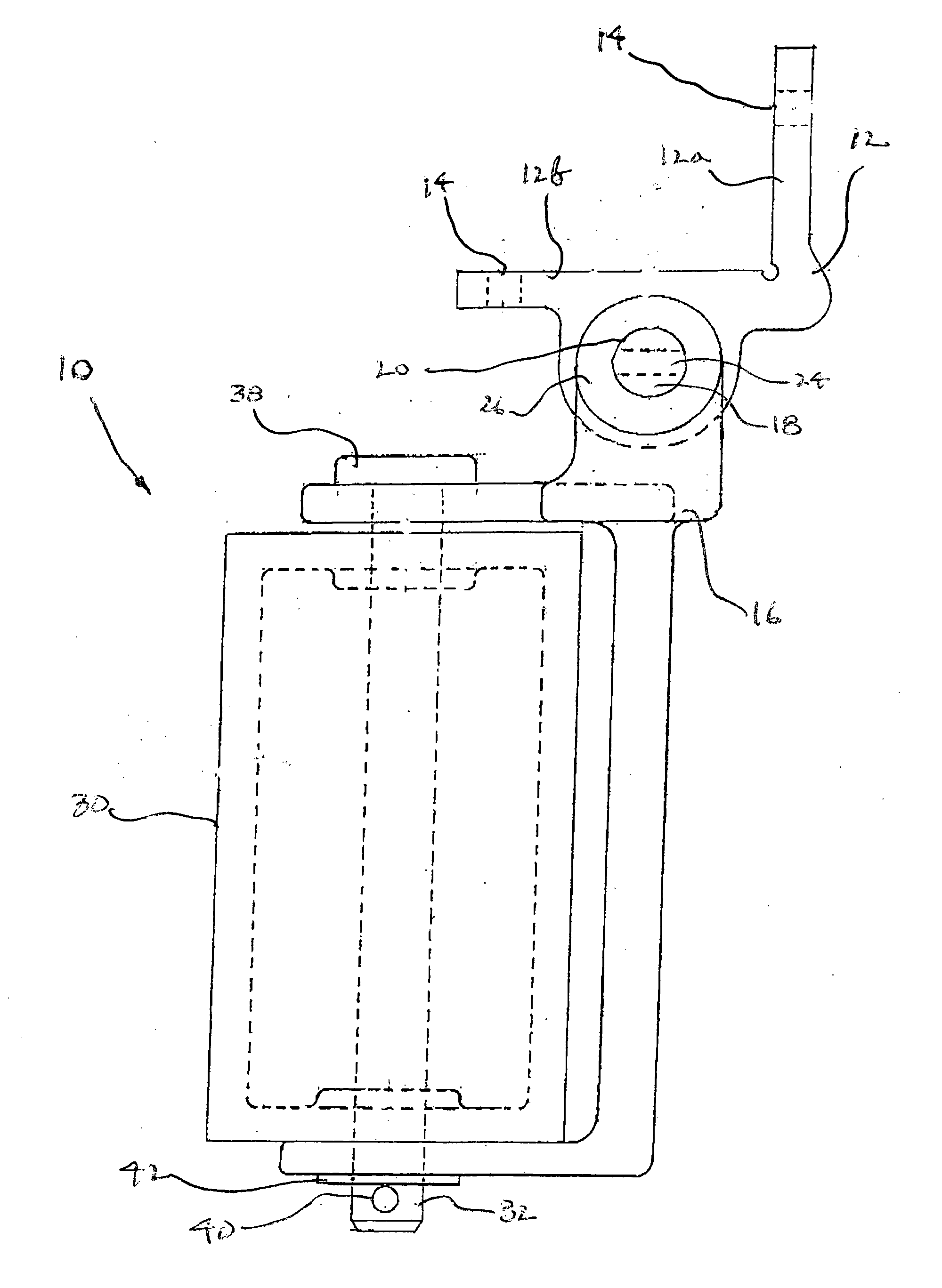
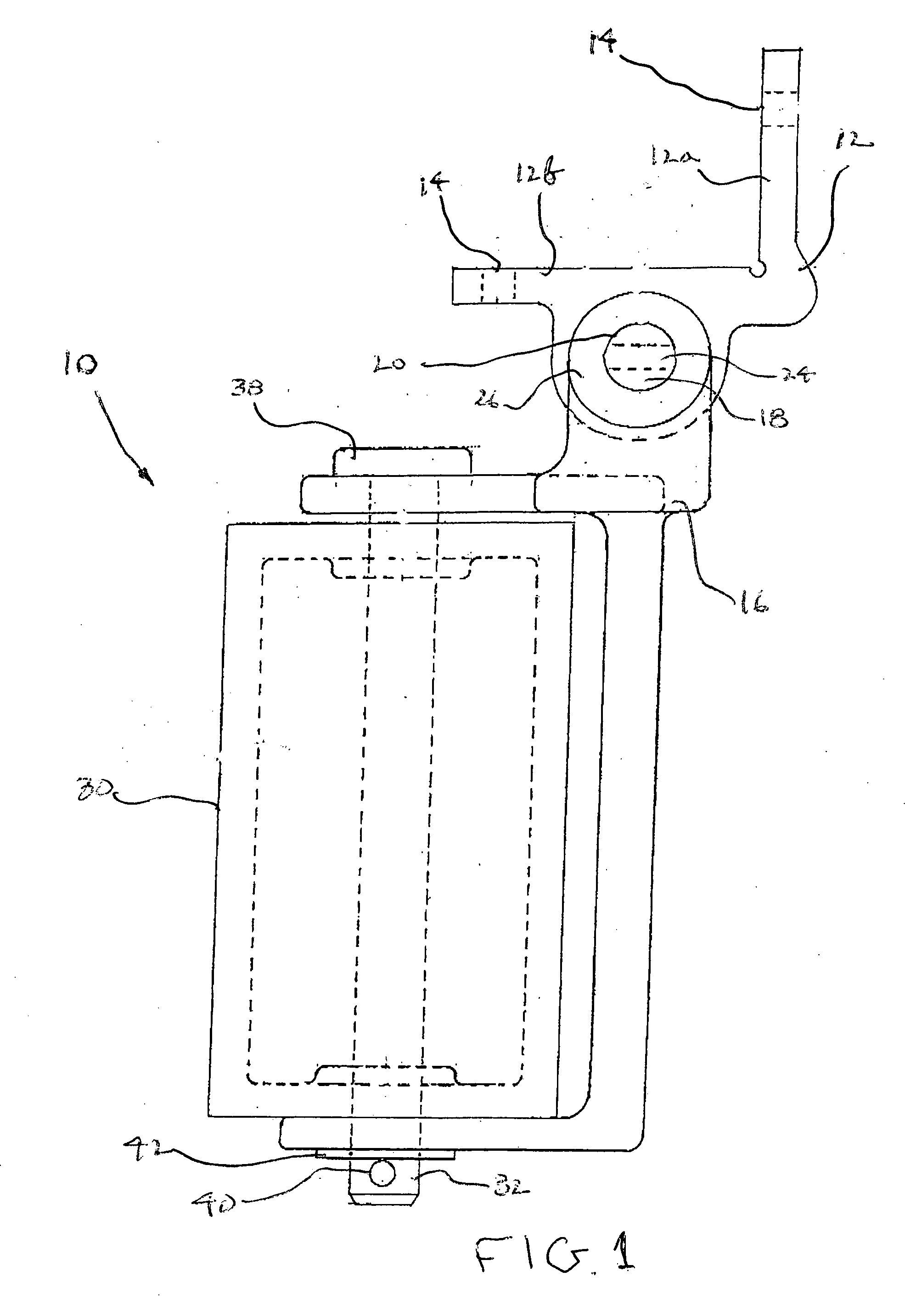
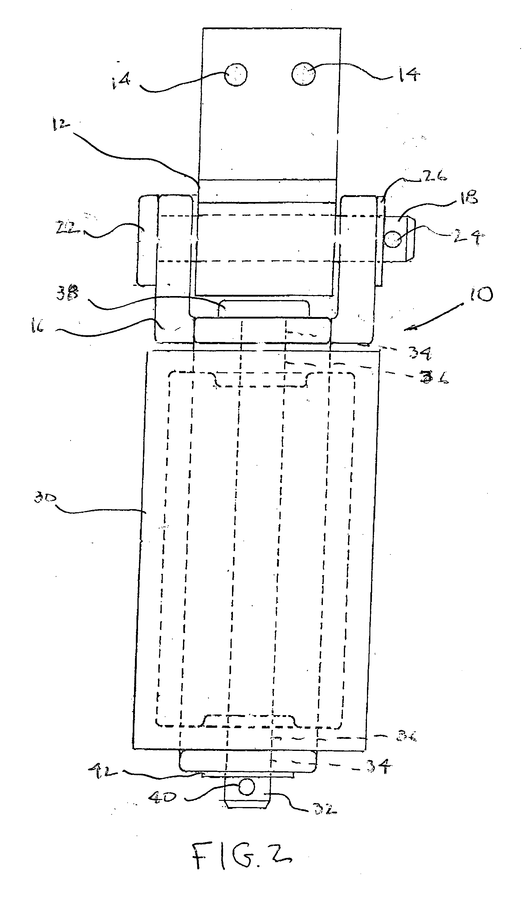
[0029] The pick-up shoe of the present invention can be clearly seen in FIGS. 1-3. Referring now to FIG. 1, a pick-up shoe, generally indicated at 10, is shown attached to an insulating bracket 12 which is rigidly affixed to a railcar by a plurality of fasteners which extend through a plurality of openings 14. Bracket 12, which consists of a first section 12a and a second section 12b perpendicular to section 12a, is coupled for rotation to a contact holder 16 by a pin 18 which passes through a pair of openings 20 within holder 16. Pin 18, which contains a head 22 and a through aperture 24, is preferably held in place by a washer 26 and a cotter pin (not shown) or the like inserted through aperture 24. Bracket 12 is constructed from a non-conductive material such as plastic or another similar polymer to electrically isolate pick-up shoe 10 from the body of the railcar.

[0030] An electrical contact 30 is rotatably fastened within contact holder 16. Contact 30, which constitutes a tubu...


PUM


Abstract

A wayside electrical pick-up shoe for operating the discharge of a railcar. The shoe includes a counterweight for biasing the shoe against the rail. The pick-up shoe uses no springs in the design.

Description

CROSS REFERENCE TO RELATED APPLICATIONS [0001] This application claims benefit from U.S. Provisional Patent Application No. 60 / 613,005, filed Sep. 24, 2004, which application is incorporated herein by reference.BACKGROUND OF THE INVENTION [0002] 1. Field of the Invention [0003] This invention relates generally to railcars, and, in particular, to an electrical pick-up shoe for use in unloading a railroad hopper car. [0004] 2. Description of the Related Art [0005] Pick-up shoes have long been utilized in the railroad industry to aid in the control of electrical systems on railroad cars. For example, U.S. Pat. Nos. 1,391,255; 2,305,241; 3,509,292; 3,740,498; 4,542,701; and 5,454,456 all teach systems in which power is supplied to the railcar by use of a pick-up shoe which is capable of contacting a trackside third rail which is energized. [0006] U.S. Pat. No. 6,227,123 teaches a pick-up shoe which includes a spring biased electrical contact pivotally attached to a base plate with a mec...

Claims


Application Information

Patent Timeline
IPC IPC(8): B60L5/38
CPCB60L5/04B60L2200/26B61D7/30B60L5/39
Inventor TAYLOR, FRED J.
Owner TAYLOR FRED J
Why Eureka
Try Eureka