Easy clean spray gun

a spray gun and cleaning technology, applied in the field of delivery systems, can solve problems such as solvent disposal problems, and achieve the effects of reducing the amount of solvent used, simplifying the cleaning of the spray gun, and reducing the amount of cleaning

Active Publication Date: 2006-03-30
3M INNOVATIVE PROPERTIES CO
View PDF34 Cites 68 Cited by
  • Summary
  • Abstract
  • Description
  • Claims
  • Application Information

AI Technical Summary

Benefits of technology

[0014] By connecting the reservoir to the spray head and arranging for the spray head to be detachable from the spray gun, cleaning of the spray gun is simplified. As a result, a reduction in the amount of solvent used to clean the spray gun may be possible.
[0015] More particularly, liquid withdrawn from the reservoir in use is delivered to the spray nozzle through the spray head body without passing through the spray gun body. In this way, the extent to which the spray gun body is contaminated by the liquid and the amount of cleaning required on completion of spraying or when changing over the spray gun to spray another liquid may be reduced.
[0016] Preferably, the spray head is disposable and can be thrown away after use. In this way, cleaning of the spray head can be avoided and the spray gun can be changed over to dispense another liquid by attaching a new spray head with a clean spray nozzle connected to a reservoir for the liquid.
[0017] The mateable formations for releasably securing the spray head to the spray gun may form a bayonet type connection that facilitates rapid connection / disconnection of the spray head with a simple push twist action. Any other suitable type of mateable formations providing a releasable connection may be employed.

Problems solved by technology

Particular problems arise when cleaning the gun to ensure no deposits are formed within the gun that may affect the operation of the gun.
This is time consuming and the use of solvents is undesirable from health and safety considerations and causes problems for disposal of the solvent after use.

Method used


Image

  • Easy clean spray gun
  • Easy clean spray gun
  • Easy clean spray gun

Examples


Embodiment Construction

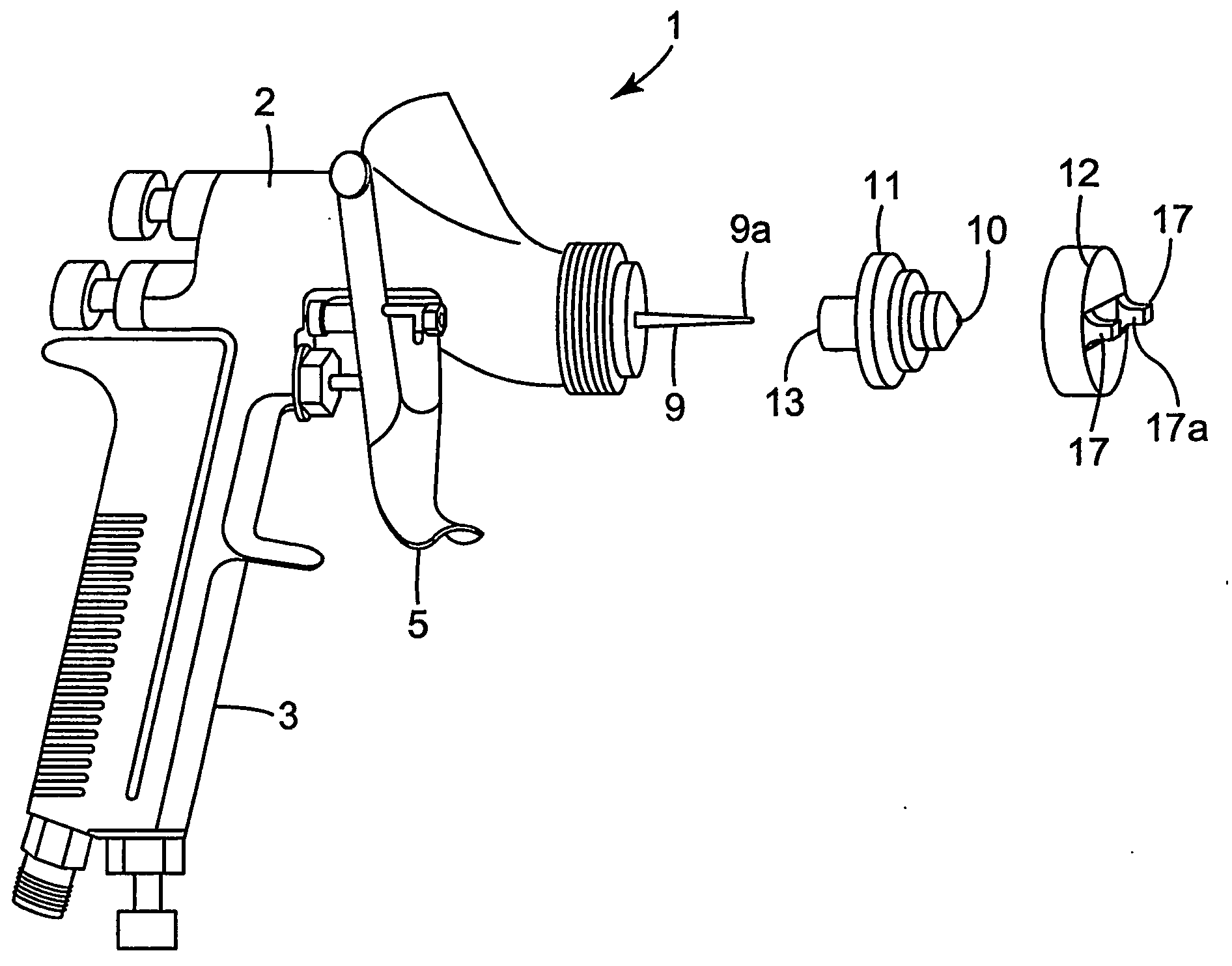
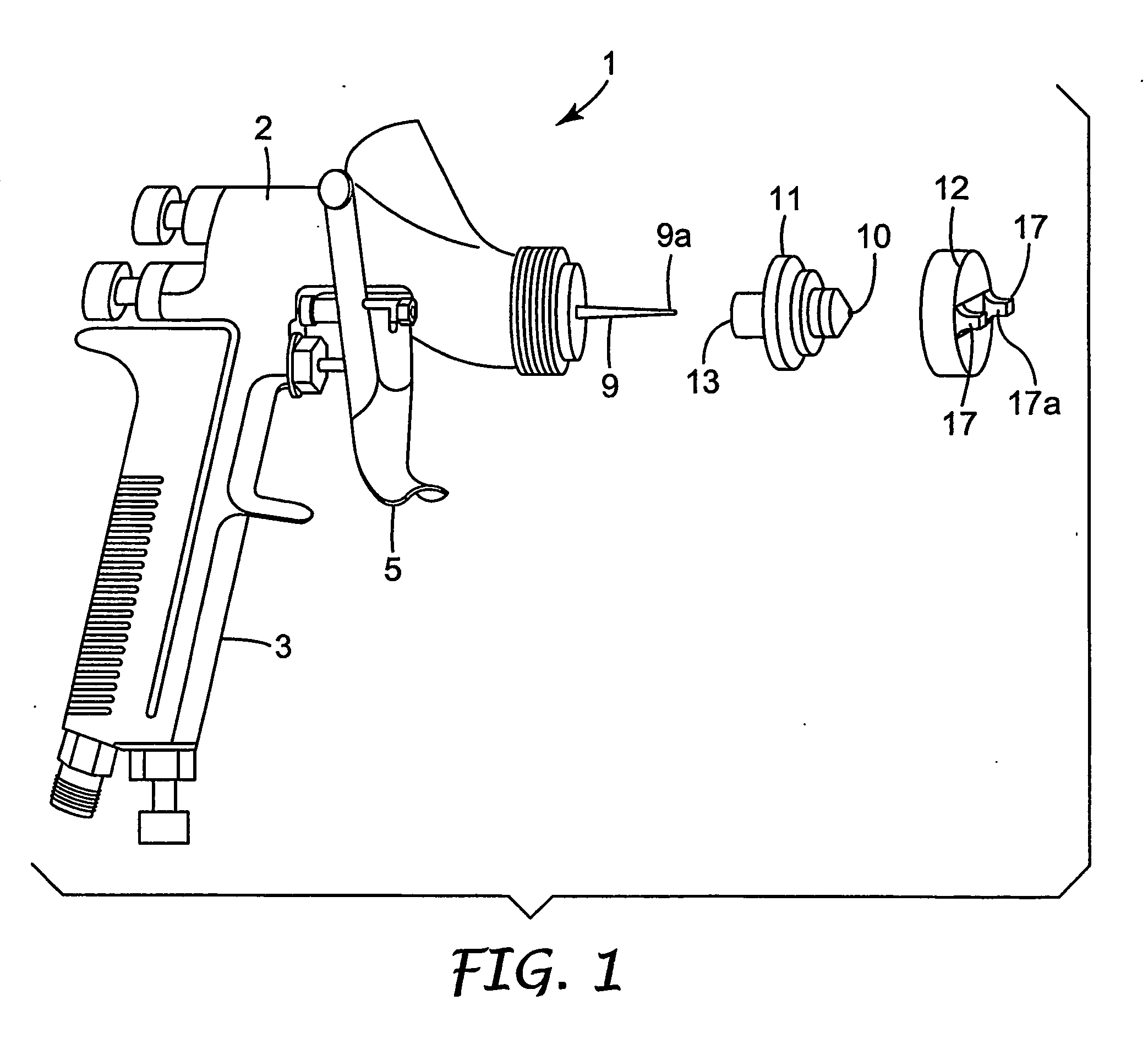
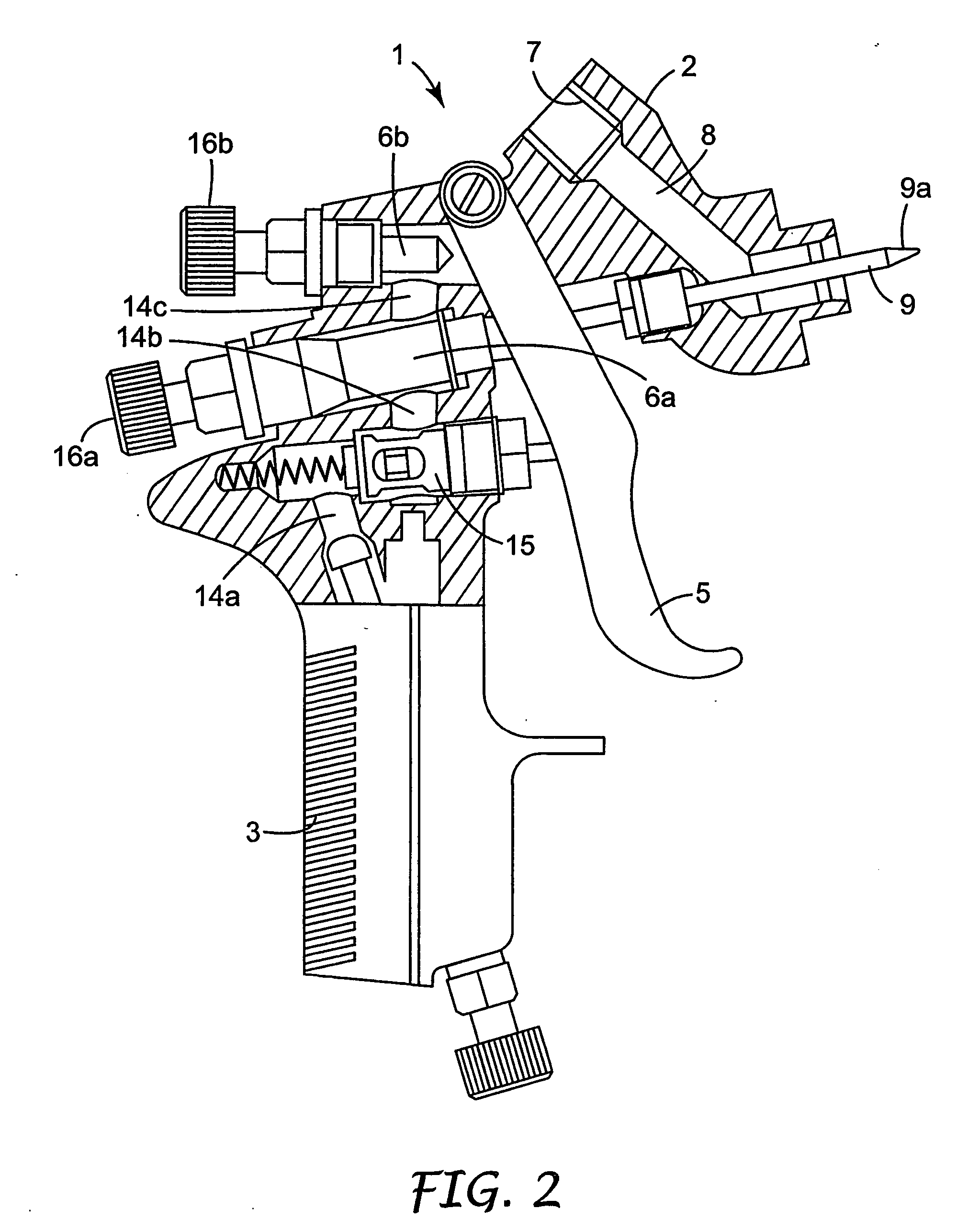
[0041] Referring first to FIGS. 1 and 2 of the accompanying drawings, there is shown a typical prior art paint spray gun 1 of the gravity feed type.

[0042] The gun 1 comprises a body 2, a handle 3 that extends downwardly from the rear end of the body 2 and a spray nozzle 4 at the front end of the body 2. The spray gun 1 is manually operable by a trigger 5 that is pivotally mounted on the sides of the gun 1.

[0043] A paint reservoir (not shown) is detachably secured to the gun 1 via an internally threaded inlet 7 on the top of the gun 1. The reservoir may have an externally threaded outlet for screwing directly into the inlet 7 or into an adaptor (not shown) screwed into the inlet 7. The reservoir may be of any known construction and provides a supply of paint to the spray nozzle 4 via an internal passageway 8 formed in the body 2 of the gun 1.

[0044] The spray nozzle 4 comprises an inner component 11 and an outer component 12 that screws onto the front end of the body 2 of the gun 1...


PUM


Abstract

A spray gun 101 has a spray head 150 connected to a body 102 of the spray gun 101 and a reservoir 156 connected to the spray head 150 for supplying liquid to a spray nozzle 153 of the spray head 150. The spray head 150 is arranged so that liquid from the reservoir 156 is delivered to the spray nozzle 153 without passing through the spray gun body 102 in response to actuation of the spray gun 101 via a trigger 105. The spray head 150 is releasably secured and can be detached from the spray gun body 102 and thrown away after use. The reservoir 156 is mounted on the spray head 150 and can be removed and thrown away with the spray head 150 after use.

Description

FIELD OF THE INVENTION [0001] This invention concerns improvements in or relating to liquid spraying apparatus such as a spray gun. More especially, the invention relates to the delivery system for the liquid to be sprayed. The invention has particular application to a spray head for reducing the amount of cleaning of the spray gun required on completion of spraying and / or when changing over the spray gun to spray a different liquid. BACKGROUND OF THE INVENTION [0002] Spray guns are widely used in vehicle body repair shops when re-spraying a vehicle that has been repaired following an accident. In the known spray guns, the liquid is contained in a reservoir attached to the gun from where it is fed to a spray nozzle. On emerging from the spray nozzle, the liquid is atomised and forms a spray with compressed air supplied to the nozzle. The liquid may be gravity fed or suction fed or, more recently, pressure fed by an air bleed line to the reservoir from the compressed air line to the ...

Claims


Application Information

Patent Timeline
Patent Type & Authority Applications(United States)
IPC IPC(8): B05B1/28
CPCB05B7/2435B05B15/02B05B7/2481B05B7/2478B05B7/2408B05B15/50
Inventor JOSEPH, STEPHEN C. P.BLETTE, RUSSELLE
Owner 3M INNOVATIVE PROPERTIES CO
Why Eureka
Try Eureka