
Image display device and image signal processing device

a display device and signal processing technology, applied in the direction of instruments, computing, electric digital data processing, etc., can solve the problems of static uneven luminance, inability to obtain good characteristics, and inability to achieve good characteristics, etc., to achieve better image display

Inactive Publication Date: 2006-03-30
KK TOSHIBA
View PDF3 Cites 23 Cited by
  • Summary
  • Abstract
  • Description
  • Claims
  • Application Information

AI Technical Summary

Problems solved by technology

However, if such a structure is adopted for a display having luminance variation among display pixels, there has been a problem that the correction of the uneven luminance and the multi-gradation processing are incompatible with each other to interfere each other due to difference in luminance characteristics among the display pixels, so that good characteristics cannot be obtained in some cases.
Moreover, an uneven luminance correction value is digital data and thus includes more or less error.
This has posed a problem that static unevenness in luminance may possibly occur.

Method used


Image

  • Image display device and image signal processing device
  • Image display device and image signal processing device
  • Image display device and image signal processing device

Examples


Embodiment Construction

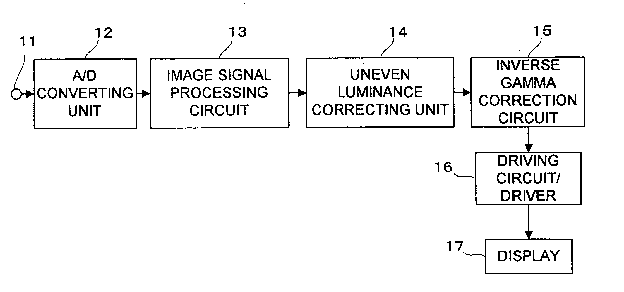
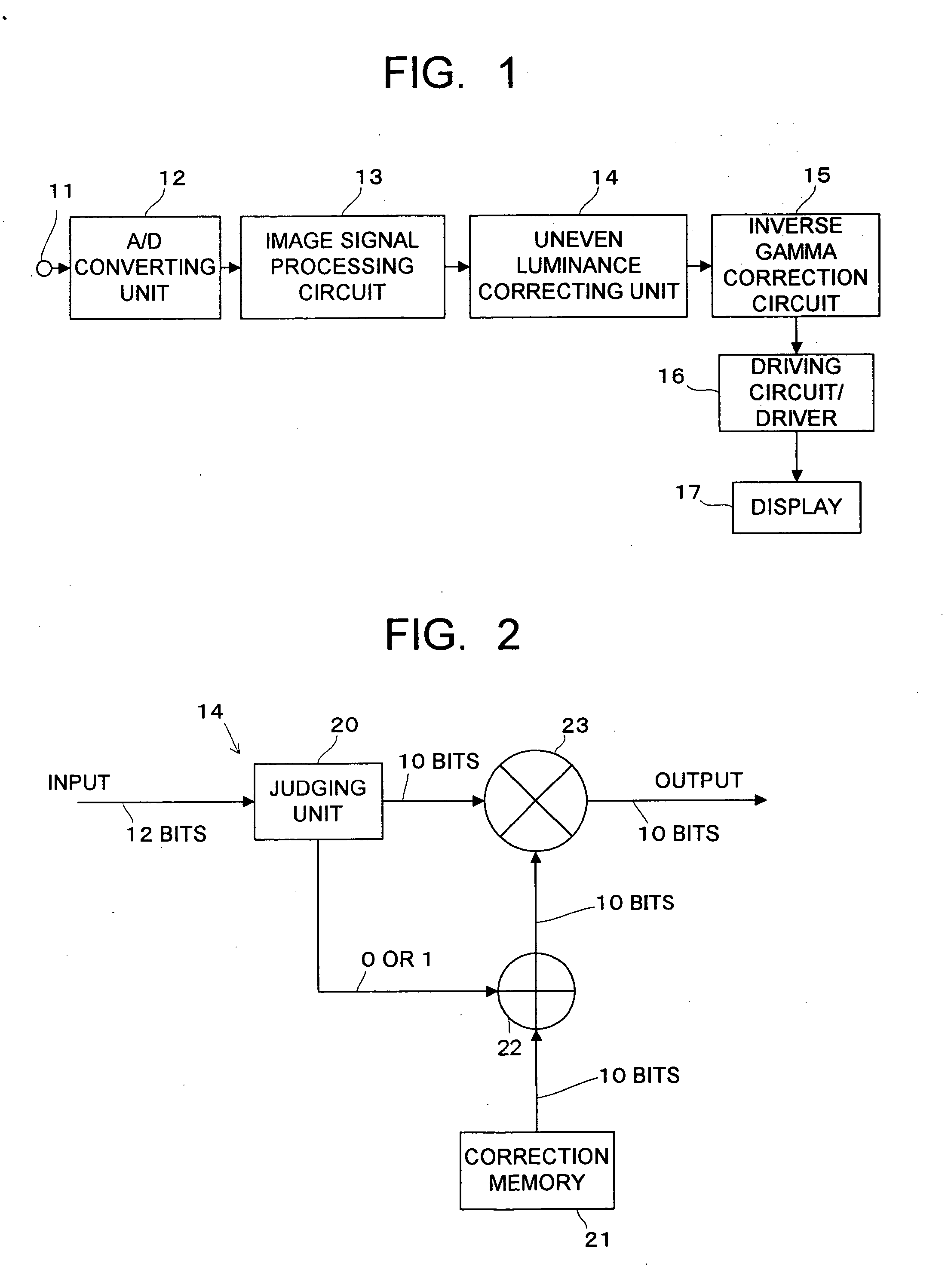
[0018] Hereinafter, embodiments of the present invention will be described with reference to the drawings. FIG. 1 schematically shows configuration of an essential part of an image display device according to one embodiment of the present invention. In FIG. 1, 11 denotes an input terminal, 12 denotes an A / D converting unit, 13 denotes an image signal processing circuit, 14 denotes an uneven luminance correcting unit, 15 denotes an inverse Gamma correction circuit, 16 denotes a driving circuit / driver, and 17 denotes a flat display as an image display unit.

[0019] An analog image signal and so on extracted from broadcast signals received by a not-shown receiving unit is inputted to the input terminal 11. The analog image signal inputted to the input terminal 11 is inputted to the A / D converting unit 12 to be converted to a digital signal here. The digital signal is next inputted to the image signal processing circuit 13 to be subjected to brightness processing, contrast processing, an...


PUM


Abstract

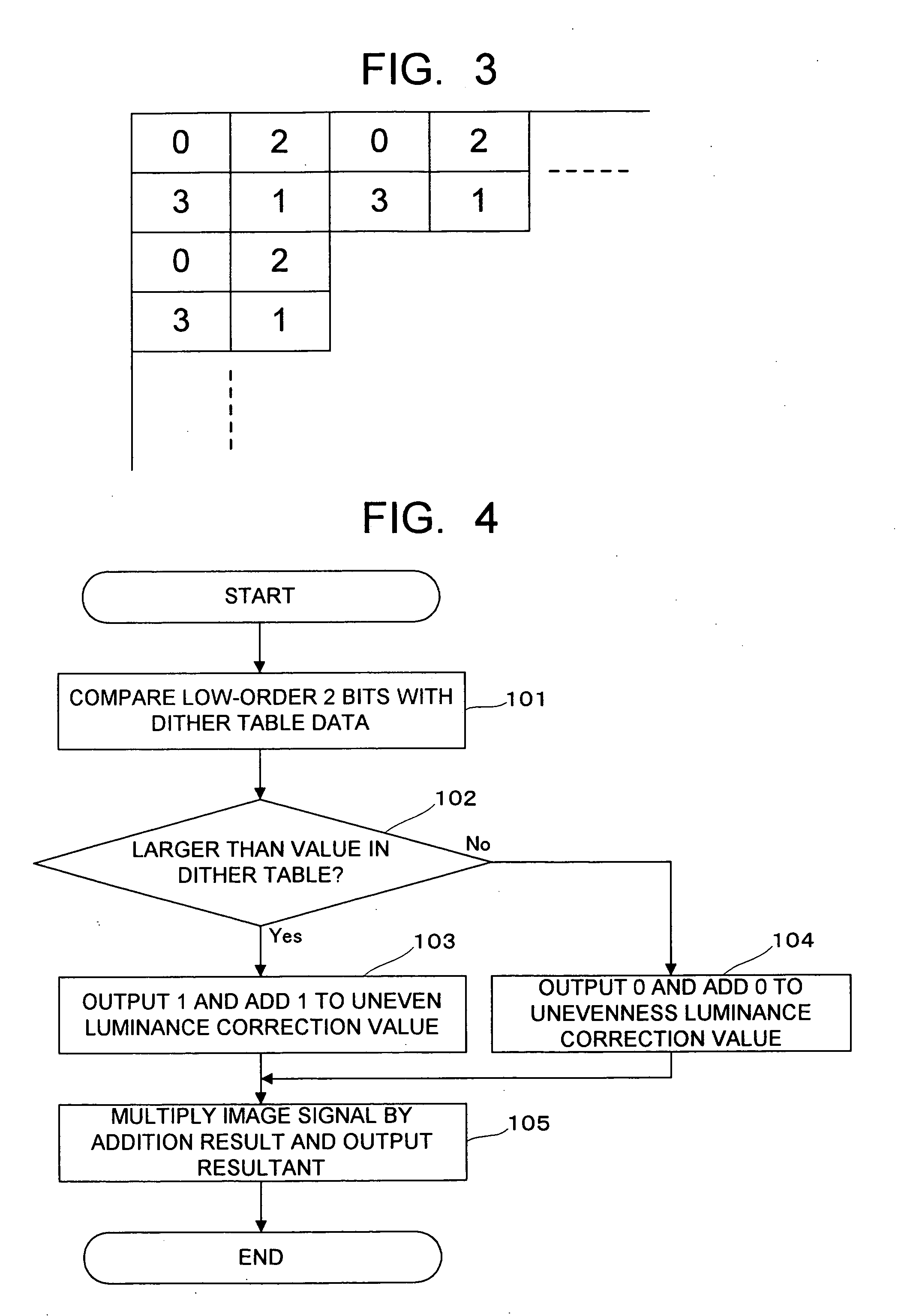
A judging unit compares data in a dither table for each display pixel with a numerical value of low-order 2 bits of an input signal (12 bits) and outputs 1 to an adder when the numerical value of the low-order 2 bits of the input signal is larger than the data in the dither table, while outputting 0 to the adder in other cases. The adder adds the value outputted from the judging unit to an uneven luminance correction value read from a correction memory, so that the uneven luminance correction value is corrected. A multiplier multiplies the input signal by the uneven luminance correction value after the correction.

Description

CROSS-REFERENCE TO RELATED APPLICATION [0001] This application is based upon and claims the benefit of priority from the prior Japanese Patent Application No. 2004-289119, filed on Sep. 30, 2004; the entire contents of which are incorporated herein by reference. BACKGROUND OF THE INVENTION [0002] 1. Field of the Invention [0003] The present invention relates to an image display device and an image signal processing device, and more particularly, to an image display device and an image signal processing device having a function of correcting variation in luminance (uneven luminance) among display pixels. [0004] 2. Description of the Related Art [0005] As an image display device, for example, a FED (field emission display) which is a flat image display device using field emission type elements has been conventionally known. In such an image display device, variation in luminance (uneven luminance) among display pixels occurs due to characteristic difference among the elements. Therefo...

Claims


Application Information

Patent Timeline
Patent Type & Authority Applications(United States)
IPC IPC(8): G09G5/10
CPCG09G3/2044G09G2320/0285G09G2320/0233G09G3/22
Inventor ARAI, TAKAYUKISAKAMOTO, TSUTOMUOBAYASHI, TOSHIOYANAMOTO, MASAOOOKAWARA, YASUHIRO
Owner KK TOSHIBA
Learn More