Apparatus and method for generating parallax image

a parallax image and apparatus technology, applied in the field of apparatus for and a method of generating parallax images, can solve the problems of difficult to provide a three-dimensional image independent, difficult to display a three-dimensional image which appears to be located in the same direction,

Inactive Publication Date: 2006-03-30
KK TOSHIBA
View PDF10 Cites 23 Cited by
  • Summary
  • Abstract
  • Description
  • Claims
  • Application Information

AI Technical Summary

Benefits of technology

[0012] It is an object of the present invention to at l

Problems solved by technology

According to the technique, however it is difficult to provide a three-dimensional image independent of the light beams at the time of the object image acquisition; for

Method used


Image

  • Apparatus and method for generating parallax image
  • Apparatus and method for generating parallax image
  • Apparatus and method for generating parallax image

Examples


first embodiment

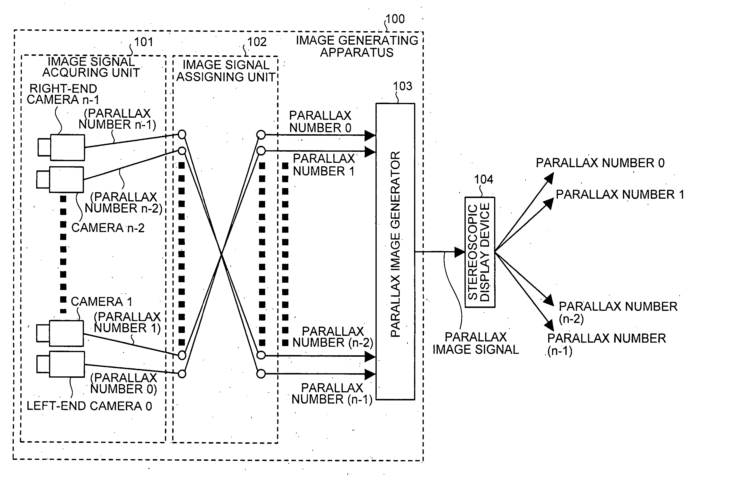
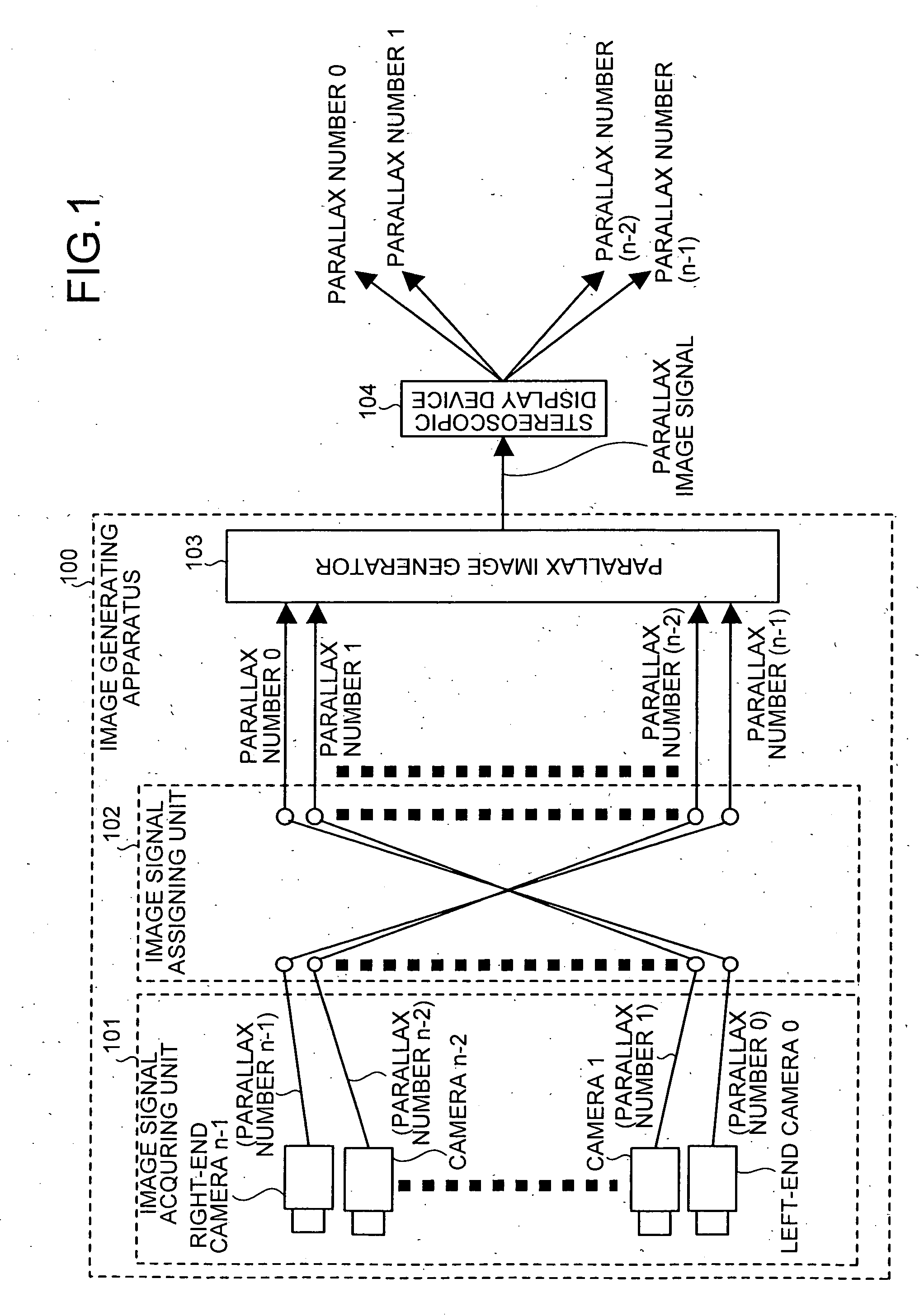
[0028] An image generating apparatus assigns a plurality of image signals obtained by image pick-up of an image object from a plurality of different parallax directions in a reverse order from an order of directions of light beams output from a three-dimensional integral imaging display (hereinafter also referred to simply as a stereoscopic display device).

[0029]FIG. 1 is a block diagram of a structure of the image generating apparatus according to the first embodiment The image generating apparatus according to the first embodiment includes an image signal acquiring unit 101, an image signal assigning unit 102, and a parallax image generator 103, and is connected to a stereoscopic display device 104 as shown in FIG. 1.

[0030] The image signal acquiring unit 101 includes a plurality of cameras 0 to n-1 that pick up images of the image object from different viewpoints and acquires the images picked up by the respective cameras as image signals to supply to the image signal assigning...

second embodiment

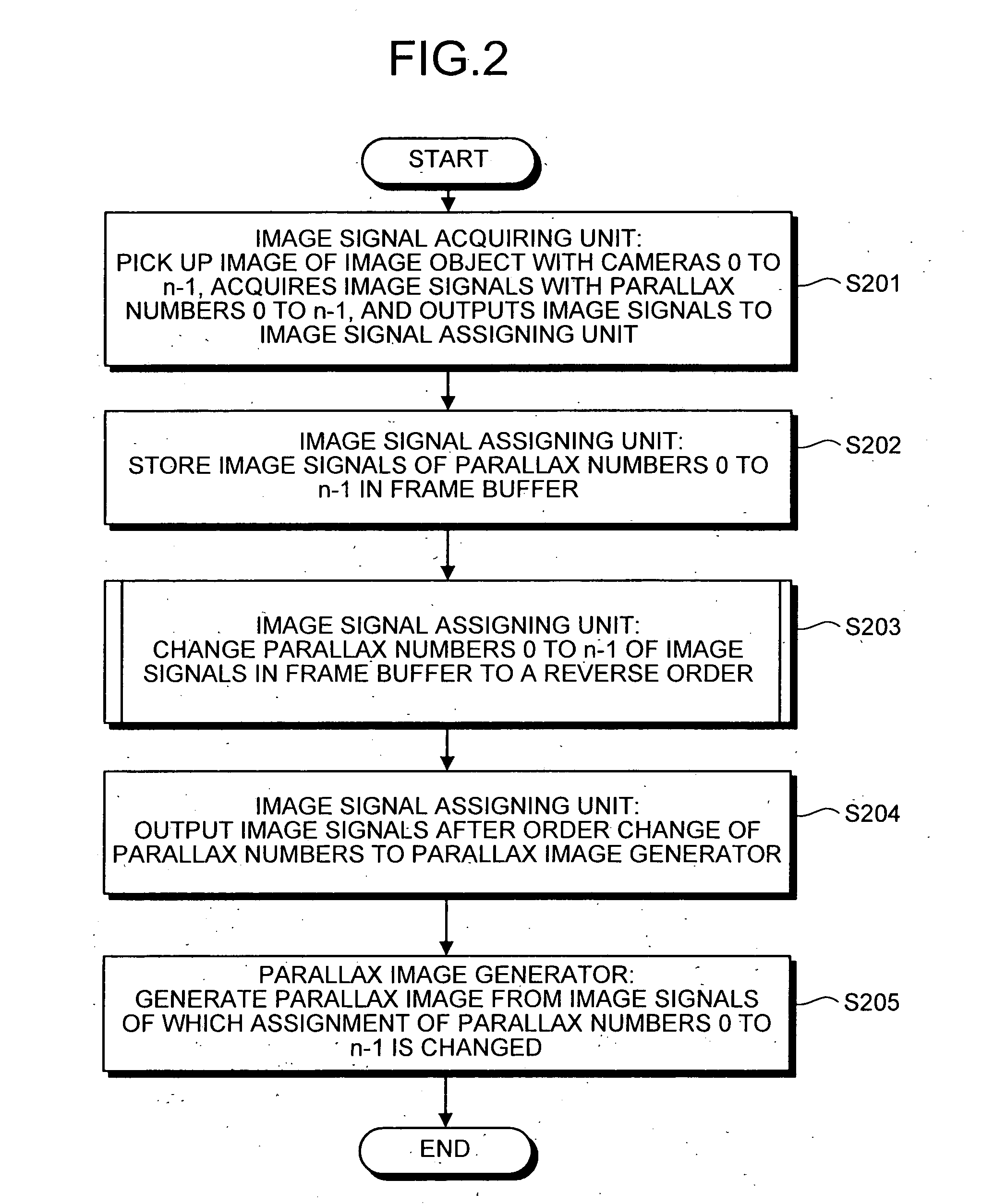
[0070] A generating process of the parallax image by the image generating apparatus 900 is explained next. FIG. 10 is a flowchart of the generating process of the parallax image.

[0071] The image signal acquiring unit 901 picks up the images of the image object from various parallax directions with the plurality of cameras 0 to n-1 to acquire the image signals of the parallax numbers 0 to n-1 from the cameras 0 to n-1 (at step S1001). Then, the image signal acquiring unit 901 stores the acquired image signals in the image signal storing unit 905 (at step S1002).

[0072] The image signal assigning unit 902 receives a direction from a user via an input device (not shown) and determines whether the received direction is a reverse order switching direction or not (at step S1003). When the received direction is the reverse order switching direction (Yes at the step S1003), the image signal assigning unit 902 acquires the image signals of the parallax numbers 0 to n-1 from the image signal...


PUM


Abstract

An apparatus for generating a parallax image to be used for a display of a three-dimensional image on a three-dimensional integral imaging display includes an image signal acquiring unit, an image signal assigning unit, and a parallax image generator. The image signal acquiring unit acquires a plurality of image signals by picking up an image of an image object from a plurality of different parallax directions. The image signal assigning unit assigns an output order of the plurality of image signal so that the plurality of image signals are arranged in a reverse parallax direction order to an order of beam directions of the three-dimensional integral imaging display. The parallax image generator generates a parallax image from the plurality of image signals to which an output order is assigned by the image signal assigning unit.

Description

CROSS-REFERENCE TO RELATED APPLICATIONS [0001] This application is based upon and claims the benefit of priority from the prior Japanese Patent Application No. 2004-285243 filed on Sep. 29, 2004; the entire contents of which are incorporated herein by reference. BACKGROUND OF THE INVENTION [0002] 1) Field of the Invention [0003] The present invention relates to an apparatus for and a method of generating a parallax image to be used for a display of a three-dimensional image on a three-dimensional integral imaging display, and a computer program product which makes a computer execute the method. [0004] 2) Description of the Related Art [0005] Conventionally, as a technique for displaying a three-dimensional image with a two-dimensional display element, integral imaging (also called as integral photography) is known (see, for example, H. Hoshino, F. Okano, H. Isono and I. Yuyama “Analysis of resolution limitation of integral photography”, J. Opt. Soc. Am, A15 (1998) 2059-2065). Accord...

Claims


Application Information

Patent Timeline
IPC IPC(8): H04N13/04H04N13/00H04N15/00H04N13/351H04N13/305H04N13/307
CPCH04N13/0242H04N13/0447H04N13/0406H04N13/0404H04N13/305H04N13/243H04N13/307H04N13/351
Inventor YANAGAWA, SHINGOYAMAUCHI, YASUNOBUTAIRA, KAZUKIFUKUSHIMA, RIEKOSAISHU, TATSUOHIRAYAMA, YUZO
Owner KK TOSHIBA
Why Eureka
Try Eureka