
Method and system for implementing a user interface for a device employing written graphical elements

Inactive Publication Date: 2006-03-30
LEAPFROG ENTERPRISES
View PDF99 Cites 78 Cited by
  • Summary
  • Abstract
  • Description
  • Claims
  • Application Information

AI Technical Summary

Benefits of technology

[0011] Accordingly, a user interface method and system that enables interaction with more complex functionality of an optical pen device having a computer system associated therewith and enables more efficient access to the different choices, options, and functions provided by the pen device, would be valuable. What is further desired is a method and interactive interface useful for interacting with an operating system resident on, or in communication with, a pen device. Embodiments in accordance with the present invention provide these and other advantages.
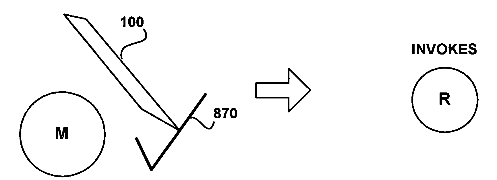
[0013] In one embodiment, the selection of a written or printed graphical element icon causes the pen device to audibly render a list of further selections that may be written and selected by the user. In this case, the first graphic element icon functions as a menu item that when selected causes the pen device to render sub-menu items related to the first graphic element icon. Any, or all, of the sub-menu items may be written on the surface and themselves selected, thereby causing the pen device to perform related functionality.

Problems solved by technology

Accessing the capabilities of increasingly powerful optical pens through the limited number and configuration of switches, buttons, etc. provided on the pen itself, or any remotely coupled computer system device, is not a satisfactory arrangement.
The drawback with this solution involves the fact that interaction and control of the functions of the pen requires real-time recognition of the user's handwriting (e.g., as the user writes the command down on a sheet of paper).
This solution is not satisfactory due to the fact that interaction with more complex functionality of an optical pen requires the user to repeatedly write-down one or more commands to access different choices, options, or functions provided by the pen.
While the solution might be satisfactory for exceedingly simple, single step type applications (e.g., “turn off”, “store”, etc.), the solution is overly cumbersome and limiting in those cases where more complex, satisfying, rich functionality is desired.

Method used


Image

  • Method and system for implementing a user interface for a device employing written graphical elements
  • Method and system for implementing a user interface for a device employing written graphical elements
  • Method and system for implementing a user interface for a device employing written graphical elements

Examples


Embodiment Construction

[0027] Reference will now be made in detail to the preferred embodiments of the present invention, examples of which are illustrated in the accompanying drawings. While the invention will be described in conjunction with the preferred embodiments, it will be understood that they are not intended to limit the invention to these embodiments. On the contrary, the invention is intended to cover alternatives, modifications and equivalents, which may be included within the spirit and scope of the invention as defined by the appended claims. Furthermore, in the following detailed description of embodiments of the present invention, numerous specific details are set forth in order to provide a thorough understanding of the present invention. However, it will be recognized by one of ordinary skill in the art that the present invention may be practiced without these specific details. In other instances, well-known methods, procedures, components, and circuits have not been described in detail...


PUM


Abstract

A method and system for implementing a user interface for a device through user created graphical elements. The method includes recognizing a graphical element icon created by a user. Once recognized, a function related to the graphical element icon is accessed and an output in accordance with the function is provided. The function is persistently associated with the graphical element icon. Menu selection and navigation is implemented through interaction with the graphic element icon. A listing of options associated with the graphical element icon is audibly rendered. In response to a selection of one of the options, the selected option is invoked.

Description

CROSS REFERENCES TO RELATED APPLICATIONS [0001] This application is a Continuation-in-Part of the co-pending, commonly-owned U.S. patent application, Attorney Docket No. 020824-004610US, Ser. No. 10 / 803,806, filed Mar. 17, 2004, by James Marggraff et al., entitled “Scanning Apparatus,” and hereby incorporated by reference in its entirety. [0002] This application is a Continuation-in-Part of the co-pending, commonly-owned U.S. patent application, Attorney Docket No. 020824-009500US, Ser. No. 10 / 861,243, filed Jun. 3, 2004, by James Marggraff et al., entitled “User Created Interactive Interface,” and hereby incorporated by reference in its entirety. [0003] This Application is related to U.S. patent application “TERMINATION EVENTS”, by Marggraff et al., filed on Jan. 12, 2005, Attorney Docket No. LEAP-P0320, that is incorporated herein in its entirety. [0004] This Application is related to U.S. patent application “PROVIDING A USER INTERFACE HAVING INTERACTIVE ELEMENTS ON A WRITABLE SUR...

Claims


Application Information

Patent Timeline
IPC IPC(8): G06K9/00
CPCG06F3/0317G06F3/03545G06F3/0481G06K9/222G06F3/0482G06F3/04883G06K9/00422G06F3/04817G06F3/0321G06V30/36G06V30/1423G06F3/0488G06F3/0354
Inventor MARGGRAFF, JAMESCHISHOLM, ALEXANDEREDGECOMB, TRACY L.
Owner LEAPFROG ENTERPRISES
Features
  • Generate Ideas
  • Intellectual Property
  • Life Sciences
  • Materials
  • Tech Scout
  • Unparalleled Data Quality
  • Higher Quality Content
  • 60% Fewer Hallucinations
Learn More