Connector and connector assembly

a technology of connectors and assemblies, applied in the direction of connection, electrical apparatus, coupling device connections, etc., can solve the problems of lock deformation away from the cavity, and achieve the effect of reducing the height of the connector, and preventing excessive lock deformation

Inactive Publication Date: 2006-03-30
SUMITOMO WIRING SYST LTD
View PDF11 Cites 12 Cited by
  • Summary
  • Abstract
  • Description
  • Claims
  • Application Information

AI Technical Summary

Benefits of technology

[0028] The escaping portion preferably penetrates the wall of the opening edge portion of the receptacle in the thickness direction. Accordingly, the height of the connector is reduced further as compared to a case where the escaping portion is a recess formed in the inner surface of the receptacle.
[0029] The housing preferably has a lock for engaging the terminal fitting. The connector may further have a retainer mountable to the housing and engageable with the terminal fitting to achieve redundant locking. The retainer is movable between a partial locking position where the terminal fitting is insertable into and withdrawable from the cavity and a full locking position where the retainer engages the terminal fitting. The retainer includes a terminal locking portion for locking the terminal fitting and an excessive deformation preventing portion at a resiliently deforming side of the lock for preventing excessive deformation of the lock when the retainer is at the partial locking position.
[0030] The absence of the wall at the deforming side of the lock creates the potential that the lock may be deformed excessively. However, the excessive deformation preventing portion prevents the excessive deformation of the lock.
[0031] The retainer preferably includes a terminal lock for locking the terminal fitting and a lock protector extending from the terminal lock substantially along the outer exposed surface of the lock. The lock protector substantially covers the lock along the longitudinal direction of the lock to achieve good overall operability.
[0032] The excessive deformation preventing portion and / or the lock protector preferably are in a resiliently deforming area of the lock to prevent deformation of the lock when the terminal lock of the retainer engages the terminal fitting.

Problems solved by technology

The lock interferes with the terminal fitting as the terminal fitting is inserted into the cavity, and hence the lock deforms away from the cavity.

Method used


Image

  • Connector and connector assembly
  • Connector and connector assembly
  • Connector and connector assembly

Examples


first embodiment

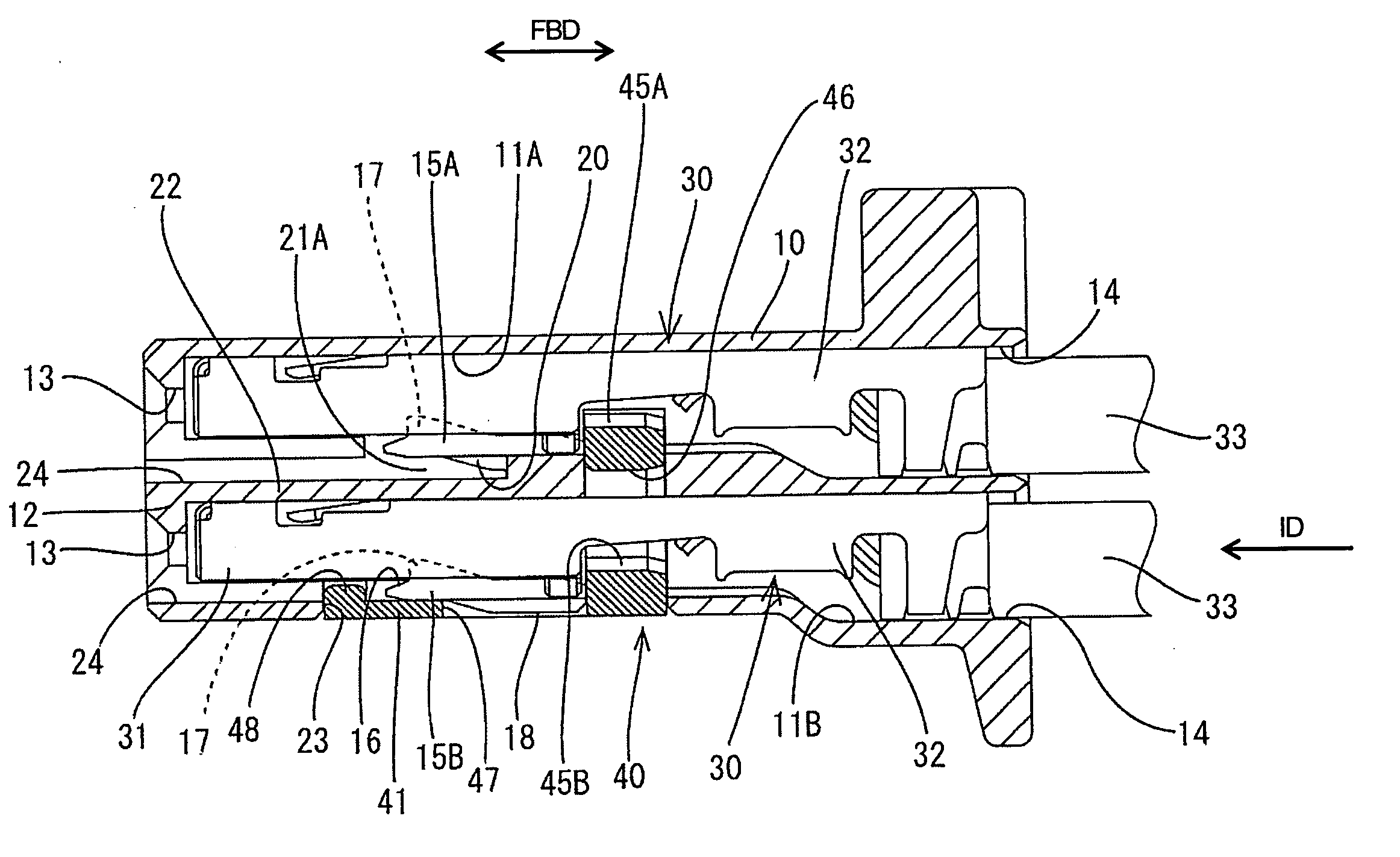
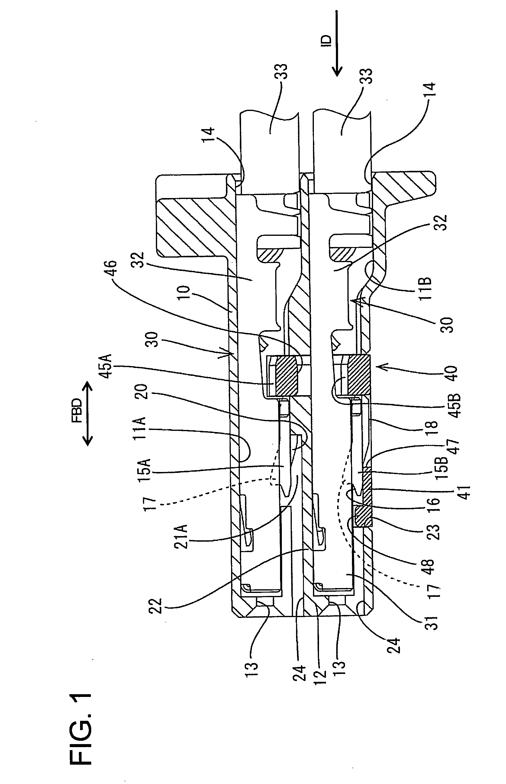
[0067] A connector according to the invention is illustrated in FIGS. 1 to 8. The connector has a housing 10 made e.g. of a synthetic resin. The housing 10 is substantially in the form of a flat block, and terminal cavities 11A, 11B are formed substantially side by side in the housing 10 at upper and lower stages. The terminal cavities 11A, 11B are narrow and long substantially along forward and backward directions (FBD), and the front ends of the terminal cavities 11A, 11B are substantially exposed at the front end surface of the housing 10 via tab insertion openings 13 penetrating a front wall 12 of the housing 10, whereas terminal insertion openings 14 are formed in the rear end surface of the housing 10. Locks 15A, 15B are formed on the bottom walls of the terminal cavities 11A, 11B and cantilever forward in an inserting direction ID of the terminal fitting 30 into the respective cavity 11A, 11B. In other embodiments the locks may define a bridge shape with supports at both ends...

second embodiment

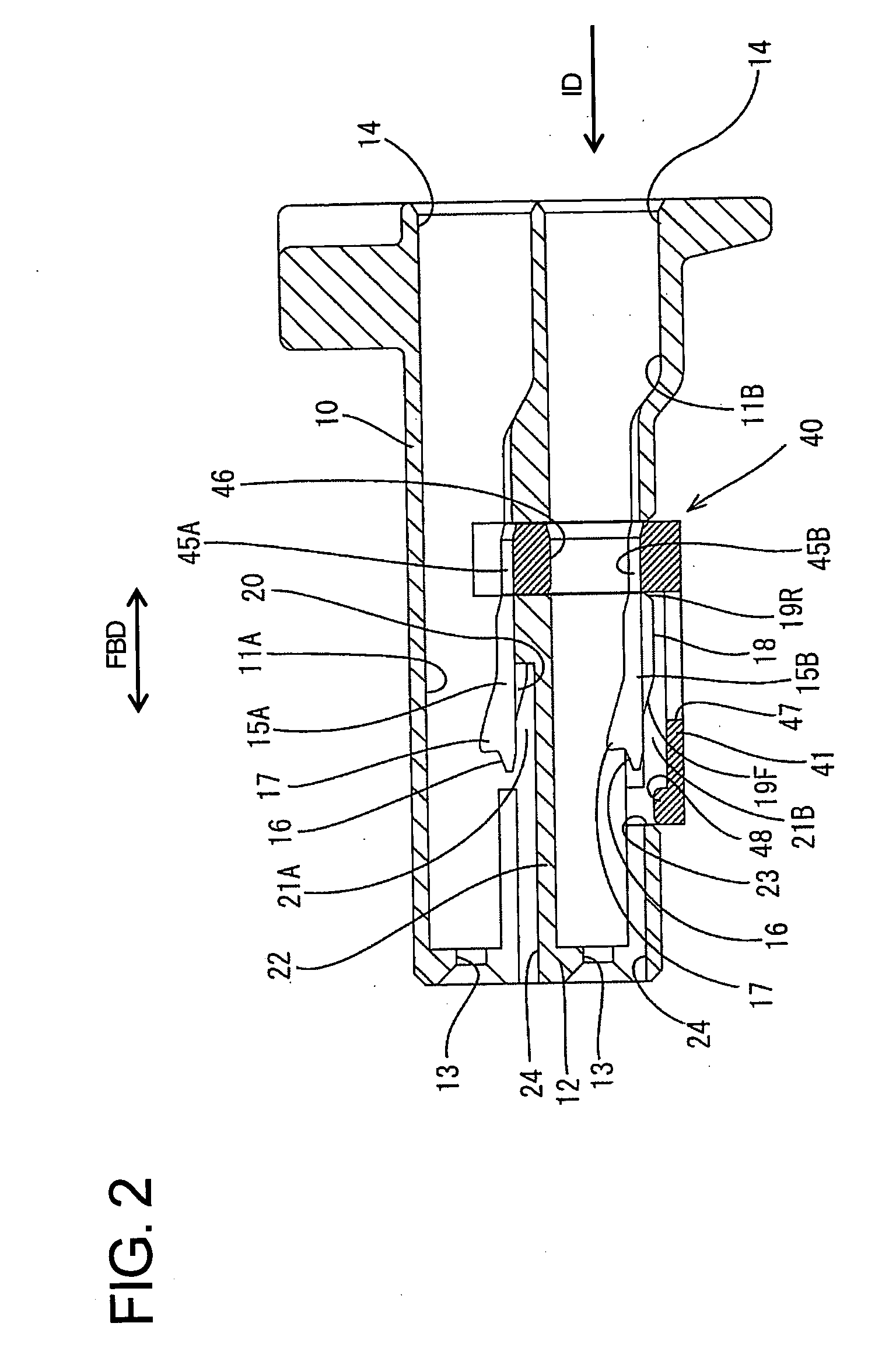
[0088] A second embodiment is described with reference to FIGS. 9 to 19. It should be understood that features similar or substantially same as in the previous embodiment are marked with the same reference numeral. The connector of this embodiment has a housing 10 e.g. made of a synthetic resin. The housing 10 is a substantially flat block with an upper stage of side by side cavities 11A and a lower stage of side by side cavities 11B. The cavities 11A at the upper stage are narrow and long along forward and backward directions FBD. The housing 10 has a front wall 12 and tab insertion openings 13 extend through the front wall 12 and into the cavities 11A. Terminal insertion openings 14 extend into the cavities 11A at the rear end of the housing 10. Locks 15A are cantilevered from the bottom walls of the cavities 11A and extend substantially forward in an inserting direction ID of the terminal fitting 30 into the respective cavity 11.

[0089] The cavities 11B at the lower stage also are...

third embodiment

[0110] the invention is illustrated in FIGS. 20 to 29 and includes a female housing 101. A resiliently deformable lock arm 103 is cantilevered rearwardly from the widthwise center of the upper surface of the female housing 101 and is configured to hold the female housing 101 connected with a male housing 102. An unlocking portion 103A is provided at the rear end of the lock arm 103 and a protection wall 105 stands at the rear edge of the upper surface of the female housing 101 over substantially the entire width. A window 104 is formed in a widthwise middle of the protecting wall 105 and the unlocking end 103A of the lock arm 103 is introduced through the window 104 for operation.

[0111] Cavities 106 are formed substantially side by side along the width direction at two stages in the female housing 101. The cavities 106 penetrate the female housing 101 in forward and backward directions FBD, and female terminal fittings 107 can be inserted into the cavities 106 from behind and along ...


PUM


Abstract

Locks (15B) are provided with reinforcing ribs (18) to partly project from surfaces of the locks (15B) facing deformation spaces (21B), and escaping portions (47) for accommodating the reinforcing ribs (18) are formed at positions facing the locks (15B) in a surface of a wall (41) facing the deformation spaces (21). The rigidity of the locks (15B) is increased by the reinforcing ribs (18). Thus, the reliability of a function of retaining terminal fittings (30) is higher. Further, in the process of inserting the terminal fittings (30), the reinforcing ribs (18) are accommodated into the escaping portions (47) as the locks (15) are deformed. This can avoid the enlargement of a connector along the deforming direction of the locks resulting from the formation of the reinforcing ribs (18).

Description

BACKGROUND OF THE INVENTION [0001] 1. Field of the Invention [0002] The invention relates to a connector and to a connector assembly. [0003] 2. Description of the Related Art [0004] EP 0 548 961 discloses a connector with a housing that has cavities for receiving terminal fittings. Locks are formed on inner walls of the cavities to engage the terminal fittings. The locks can be thinned to reduce the size of the connector. However, the thinner locks are less rigid and may hold the terminal fittings less securely. [0005] EP 0 548 961 discloses another connector with a housing that has cavities for receiving terminal fittings. Locks are formed on inner walls of the cavities to engage the terminal fittings. A jig can be inserted through a jig insertion opening in the front of the housing and into a deformation space for the lock. The jig can deform the lock resiliently in a direction to disengage the lock from the terminal fitting. The locks, the deformation spaces and the jig insertion...

Claims


Application Information

Patent Timeline
Patent Type & Authority Applications(United States)
IPC IPC(8): H01R13/514
CPCH01R13/4362H01R13/4223
Inventor KOJIMA, EIJI
Owner SUMITOMO WIRING SYST LTD
Why Eureka
Try Eureka