Surgical anchor device

a surgical and anchoring technology, applied in the direction of ligaments, prosthesis, osteosynthesis devices, etc., can solve the problems of increasing the position of other teeth, and achieve the effect of facilitating the introduction of torque and suitable structur

Inactive Publication Date: 2006-03-30
STRYKER EURO OPERATIONS HLDG LLC
View PDF4 Cites 43 Cited by
  • Summary
  • Abstract
  • Description
  • Claims
  • Application Information

AI Technical Summary

Benefits of technology

[0011] The clamping device may have a rotary element which can rotate relative to the locating region and at which the first surface is formed. The rotary element expediently has a suitable structure (e.g. an internal or external polygon, a recess or cross recess, etc.) which facilitates the introduction of a torque into the rotary element.

Problems solved by technology

However the disadvantage in this respect is that this other tooth also gradually changes its position on account of the counterforce acting on it.
This is undesirable in most cases.

Method used


Image

  • Surgical anchor device
  • Surgical anchor device
  • Surgical anchor device

Examples


first embodiment

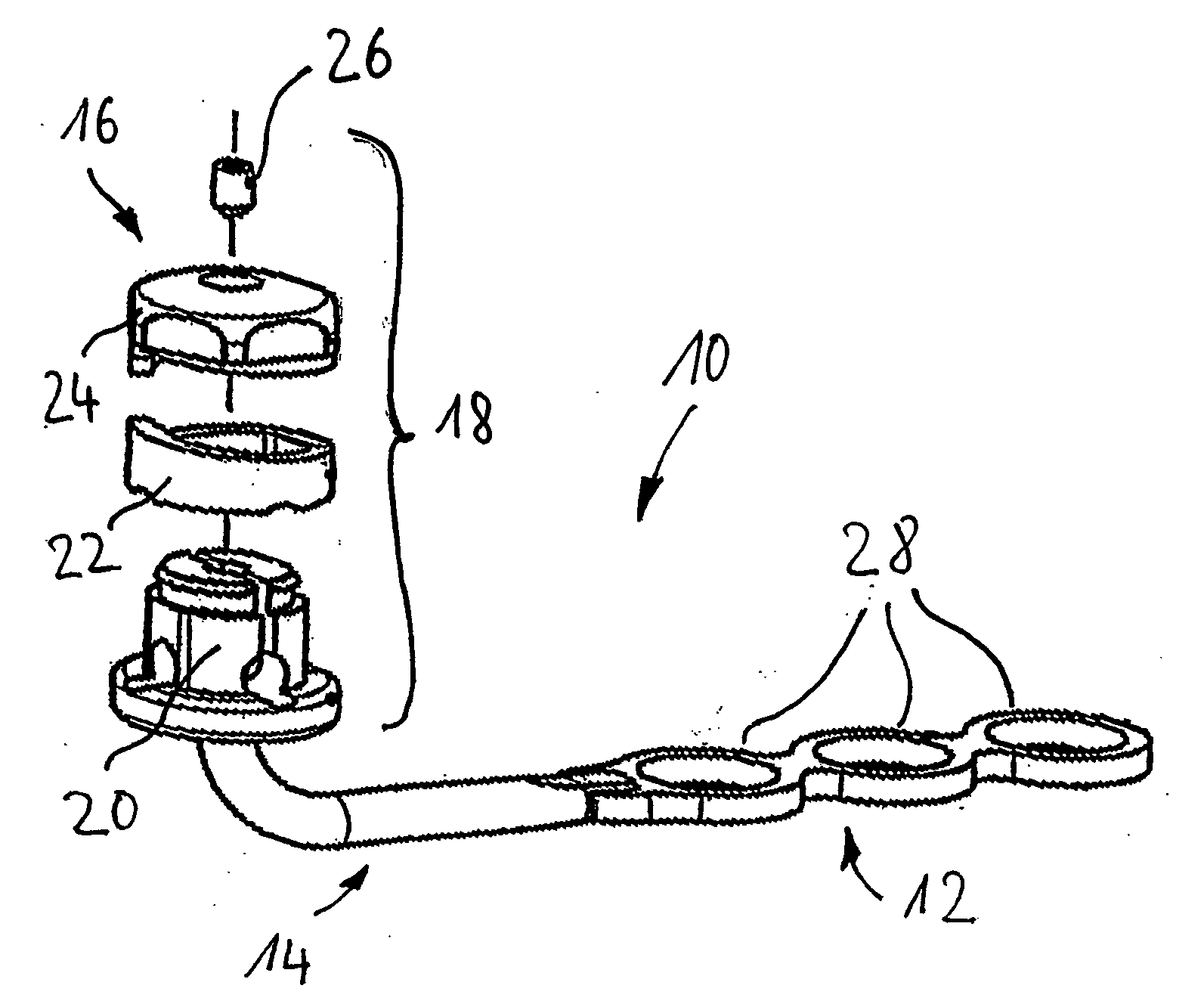
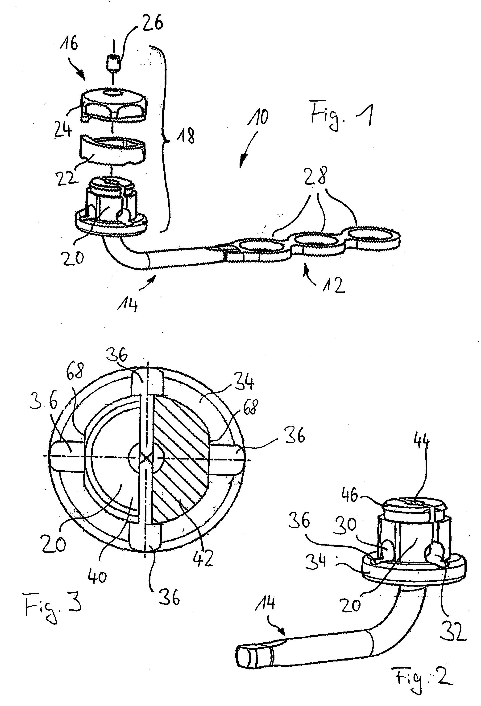
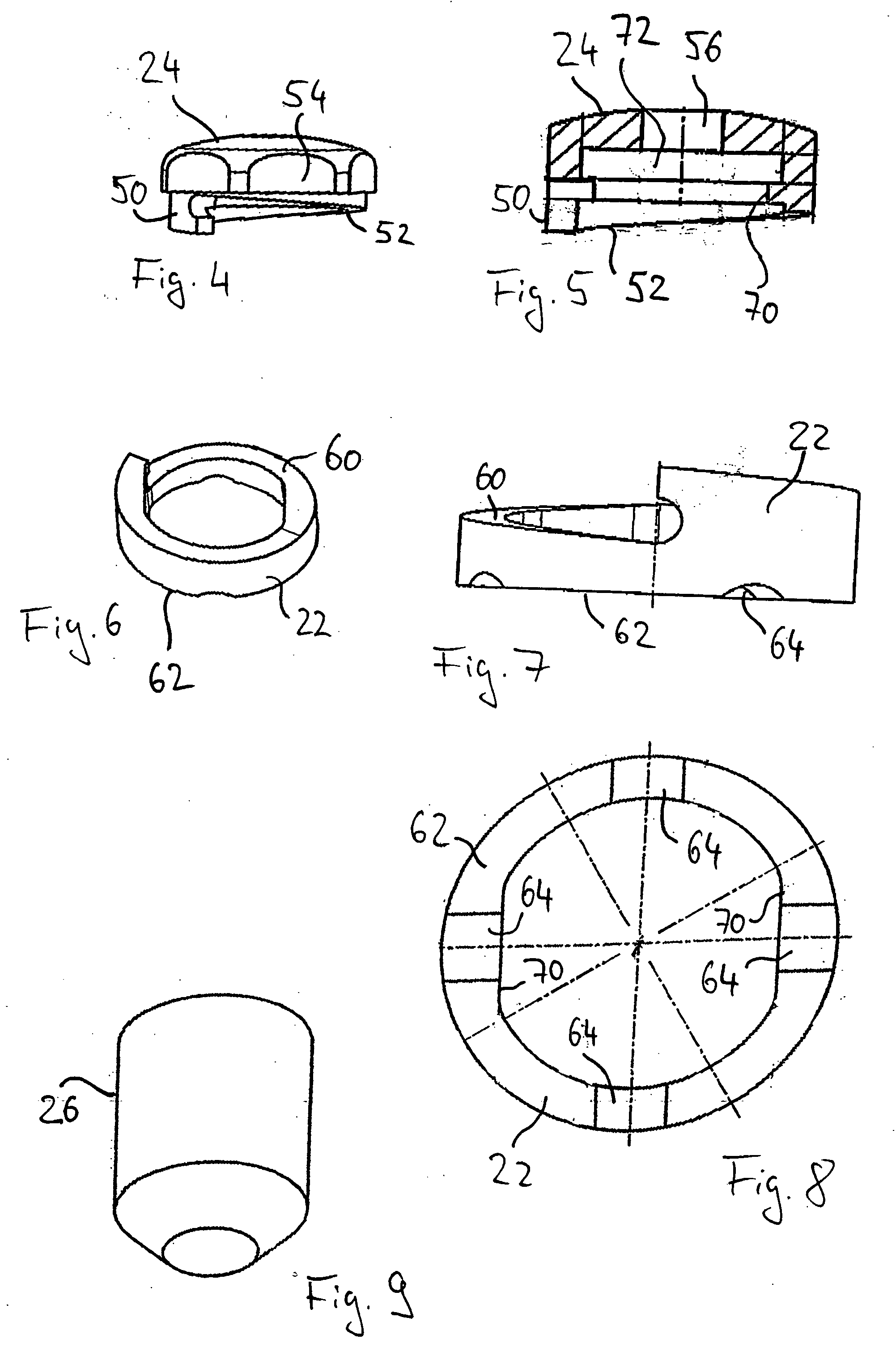
[0038]FIG. 1 shows an anchor device 10 according to the invention in an exploded representation. The anchor device 10 comprises a fixing device, which can be fixed to a bone, in the form of a bone plate 12 as well as a head 16 coupled to the bone plate 12 via an L-shaped intermediate piece 14. A clamping device 18, which consists of a plurality of components, is formed at the head 16. To be more precise, the clamping device 18 comprises a plurality of locating regions for traction elements (without reference numbers in FIG. 1) which are formed at a base body 20 of the head 16, a clamping element 22, a rotary element 24 formed as a cap as well as a locking bolt 26. The structure of these components as well as their mode of operation are explained in detail in the following.

[0039] As can be seen in FIG. 1, the bone plate 12 is of a linear (I-shaped) form with three through-openings 28 disposed one behind the other. Each of these through-openings 28 serves to locate a bone screw (not r...

second embodiment

[0058] an anchor device 10 according to the invention is represented in FIGS. 11 to 15. The anchor device 10 according to the second embodiment has many features in common with the anchor device according to the first embodiment. For example, the fixing device is again a bone plate 12, although this has a V-shaped form. In other words, the total of five through-openings 28 of the bone plate 12 are disposed in the shape of a V. These circumstances are represented in FIGS. 11 and 15.

[0059] The bone plate 12 is connected by means of a stem-shaped intermediate piece 14 to a head 16, at which a clamping device 18 is in turn formed. The clamping device 18 serves to fasten a wire-shaped traction element 80 to the head 16 of the anchor device 10.

[0060] The clamping device 18 comprises openings 30, 32 formed in a base body 20 of the head 16 for locating the traction element 80 as well as an oblique surface 52, which is formed in the region of a rotary element 24. The rotary element 24 is pr...


PUM


Abstract

An orthodontic anchor device (10) for a surgical traction element is described. The anchor device comprises a fixing device (12), which can be fixed in or to a bone in the mouth region, as well as a clamping device (18) coupled to the fixing device (12). The clamping device (18) has at least one locating region for the traction element as well as an oblique surface which can rotate relative to the locating region or which co-operates with a rotatable element. In order to produce a clamping force which fixes the traction element, a relative rotation takes place between the oblique surface and the rotatable element or between the oblique surface and the locating region.

Description

FIELD OF THE INVENTION [0001] The invention relates to a device for anchoring a surgical traction element in the mouth region. Anchor devices of this kind are frequently used for orthodontic purposes. BACKGROUND OF THE INVENTION [0002] The object of orthodontic operations is to treat tooth irregularities. Tooth irregularities are often treated by exerting tractive or compressive forces on the teeth which are to be treated. For this purpose a first end of a surgical element for exerting a tractive or compressive force (called a traction element in the following for the sake of simplicity) is fastened to a tooth which is to be treated. The other end of the traction element was in the past frequently fixed to another tooth. However the disadvantage in this respect is that this other tooth also gradually changes its position on account of the counterforce acting on it. This is undesirable in most cases. [0003] This was the reason for the development of anchor devices so as to avoid havi...

Claims


Application Information

Patent Timeline
Patent Type & Authority Applications(United States)
IPC IPC(8): A61F2/30
CPCA61C7/285A61C8/0096A61C8/0031A61C7/00A61C7/12
Inventor KNOPFLE, CHRISTIAN
Owner STRYKER EURO OPERATIONS HLDG LLC
Why Eureka
Try Eureka