Medical instrument
a technology for medical instruments and sutures, applied in the field of medical devices, can solve the problems of affecting the operation of the patient, affecting the safety of patients, and the diameter of the outer cylinder becomes disadvantageously large, so as to improve the operation and safety
- Summary
- Abstract
- Description
- Claims
- Application Information
AI Technical Summary
Benefits of technology
Problems solved by technology
Method used
Image

Examples
first embodiment
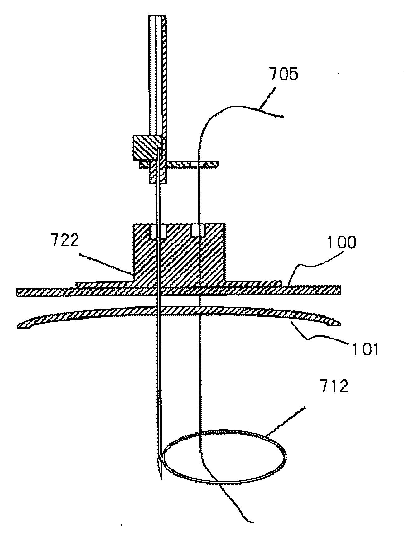
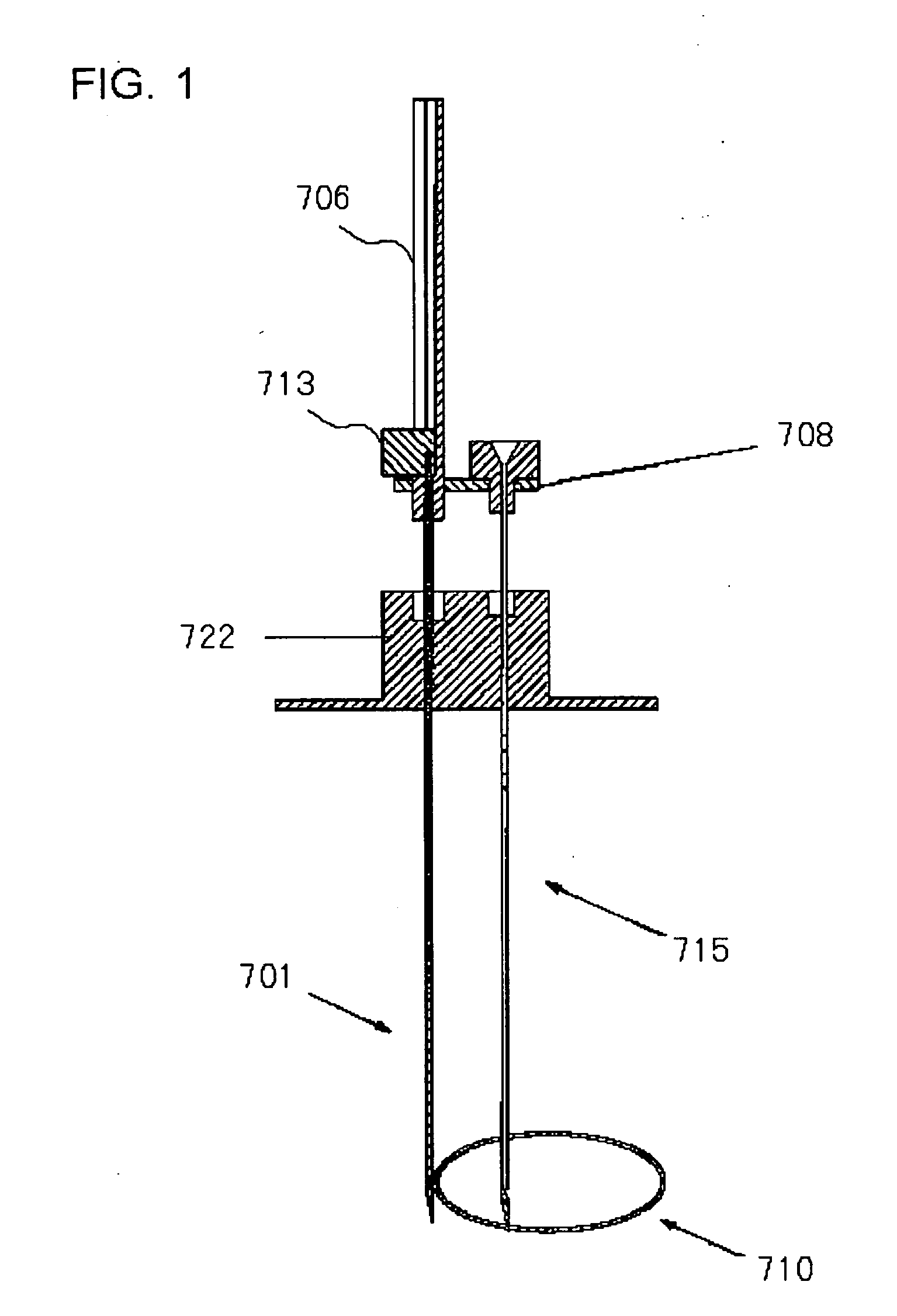
[0096]FIG. 1 is a sectional view that depicts a configuration of a medical device according to the present embodiment. The medical device shown in FIG. 1 includes a suture grasping needle 701, a guide material 706, a fixing member 708, a suture traction tool 710, a suture insertion needle 715, and an abutment member 722. This medical device can be used as, for example, an abdominal wall-to-stomach wall fixing tool.
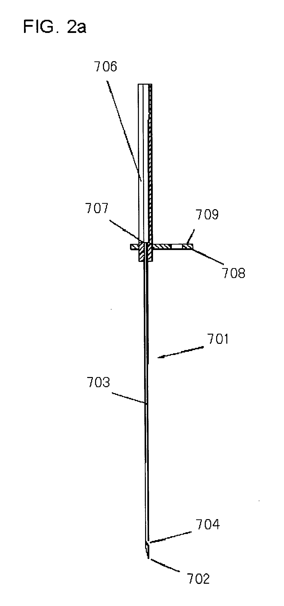
[0097]FIGS. 2a to 2c depict a configuration of the suture grasping needle 701 and those of peripheral members of the puncture needle 701. FIG. 2a is a sectional view that depicts a state in which the suture grasping needle 701 is combined with the guide material 706 and the fixing member 708. FIG. 2b is a sectional view that depicts a configuration of the suture traction tool 710. FIG. 2c is a sectional view that depicts a state of combining FIGS. 2a and 2b.
[0098] As shown in FIGS. 2a to 2c, a rod 711 and a snare 712 of the suture traction tool 710 are configured to be a...
second embodiment
[0147]FIG. 17 is a perspective view that depicts a configuration of a medical device according to the present embodiment.
[0148] A medical device 1 shown in FIG. 17 includes a main body 2, a suture insertion needle 3 into which a suture can be inserted, and a suture grasping needle 4 which is provided to be proximate to the suture insertion needle 3 and into which a suture traction tool can be inserted. The suture insertion needle 3 and the suture grasping needle 4 are detachably attached to the main body 2 by attachment and detachment means.
[0149] In this embodiment and a third embodiment, the suture insertion needle 3 corresponds to the suture insertion needle 715 (shown in FIG. 1) of the medical device according to the first embodiment. The suture grasping needle 4 corresponds to the suture grasping needle 701 (shown in FIG. 1) of the medical device according to the first embodiment.
[0150] The respective constituent elements of the medical device 1 will be described.
[0151]FIG....
third embodiment
[0219] The medical device according to the first or second embodiment can include a plurality of suture insertion needles. An instance in which the medical device according to the second embodiment includes two puncture needles will be described.
[0220]FIG. 32 is a perspective view that depicts a configuration of a medical device 11 according to the present embodiment. As shown in FIG. 32, the medical device 11 includes a main body 2, a suture insertion needle 3 and a suture insertion needle (third puncture needle) 6, which are supported by the main body 2 and into which a suture can be inserted, and a suture grasping needle 4 which is provided to be proximate to the suture insertion needles 3 and 6 and into which a suture traction tool can be inserted. The suture insertion needles 3 and 6 and the suture grasping needle 4 are detachably attached to the main body 2 by attachment and detachment means.
[0221] This medical device 11 is configured so that the suture insertion needle 6 is...
PUM
 Abstract
Description
Claims
Application Information
 - R&D Engineer
- R&D Manager
- IP Professional
- Industry Leading Data Capabilities
- Powerful AI technology
- Patent DNA Extraction
Browse by: Latest US Patents, China's latest patents, Technical Efficacy Thesaurus, Application Domain, Technology Topic.
© 2024 PatSnap. All rights reserved.Legal|Privacy policy|Modern Slavery Act Transparency Statement|Sitemap