Locking device

a technology of locking device and lock, which is applied in the direction of building locks, non-mechanical controls, interlocking clutches, etc., can solve the problems of affecting the operation of the safe, complicated electronics, and the inability to prevent a certain damage or at least increase the wear of the drive, so as to achieve a simple and reliable mechanism

Inactive Publication Date: 2006-04-06
KABA AG
View PDF22 Cites 4 Cited by
  • Summary
  • Abstract
  • Description
  • Claims
  • Application Information

AI Technical Summary

Benefits of technology

[0008] It is therefore an object of the invention to provide a locking device overcoming disadvantages of prior art locking devices, which locking device especially provides a simple and reliable mechanism to avoid situations where the drive is overloaded. Preferably, the mechanism should be such that the locking device automatically starts to be operational again once the blocking is eliminated.

Problems solved by technology

A blocked lock in a locked safe, for example constitutes a major problem for the safe's owner.
A frequent cause of failure is a blocking of the bolt due to some irregularity or because a locking member to be blocked or released by the bolt is not in a defined end position.
A blocking of the bolt may cause electrical motors driving the bolt to run in an overload mode, ultimately leading to overheating etc.
One disadvantage of such conventional overload switches are that they require a complicated electronics that has to be placed—for security reasons—inside the locked object, which electronics is a further potential reason for failure.
Further, such overload switches are activated only when a certain threshold current or temperature is exceeded, and they therefore cannot prevent a certain damage or at least increased wear to the drive caused by overload before the threshold value is reached.
This however, in situations where the blocking remains for a long time, causes a high consumption of electricity by the drive that is almost always battery powered.
However, such a switch may shift over the years, causing failures.
They also require additional long transmission lines between switch and locking device.
Also, such a switch may not detect failures caused by some irregularities.

Method used


Image

  • Locking device
  • Locking device
  • Locking device

Examples


first embodiment

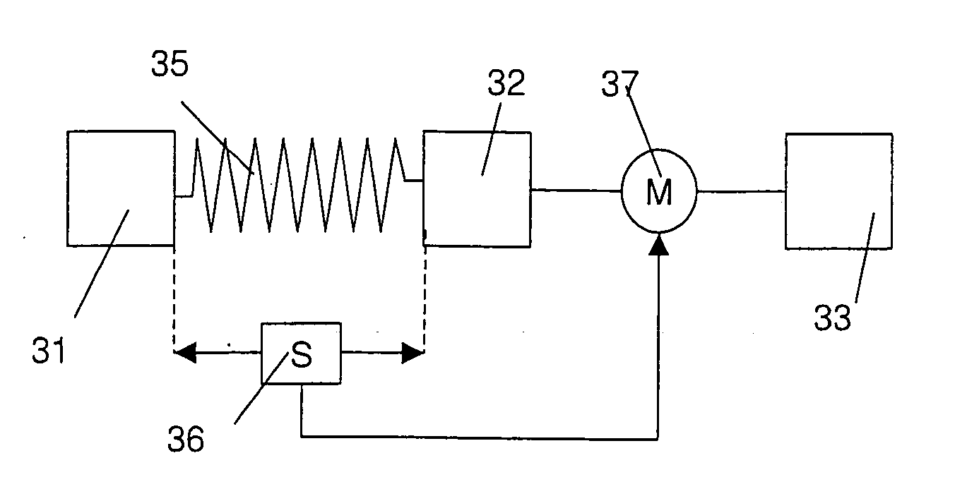
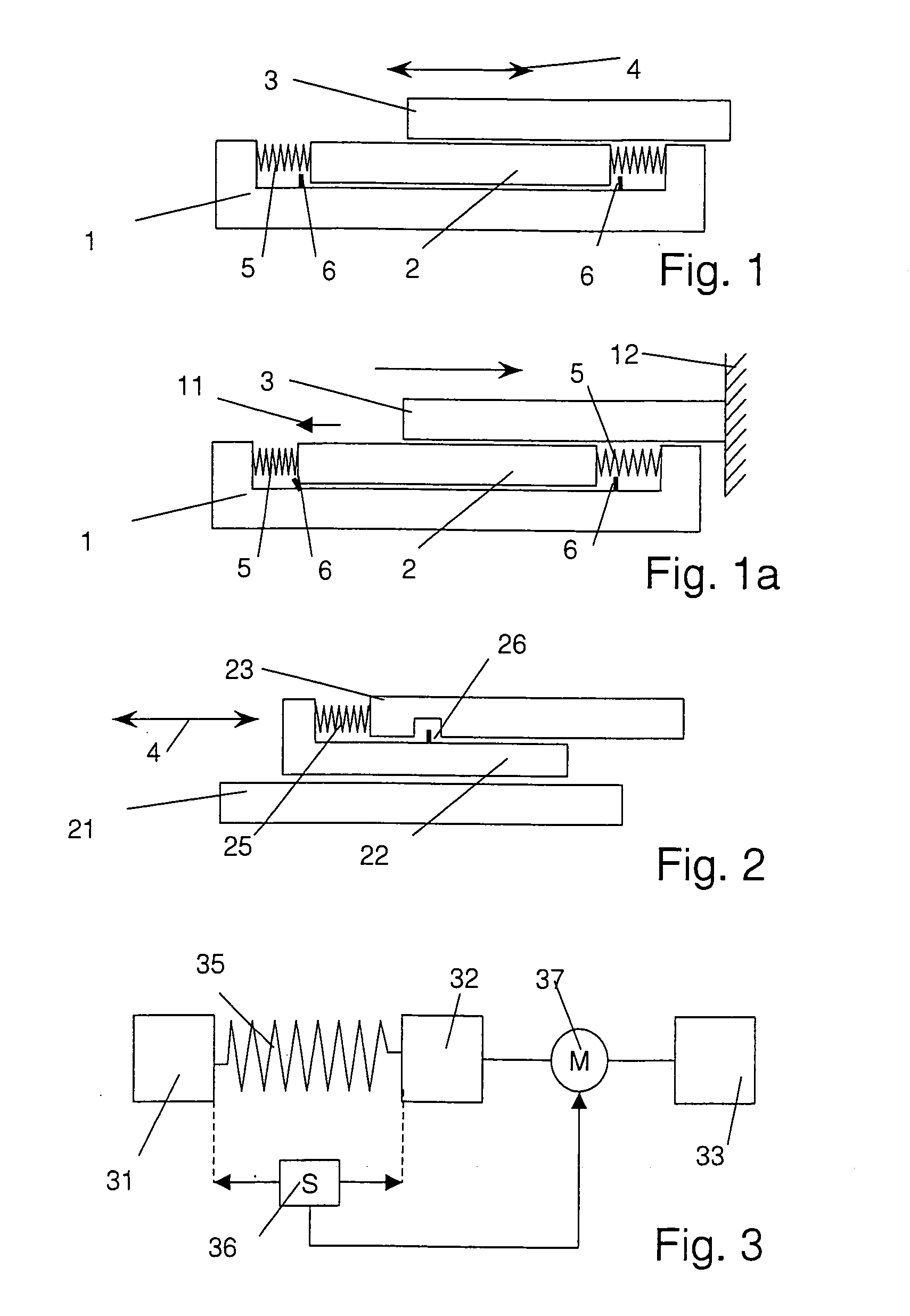
[0044]FIG. 1 depicts a very schematic picture of a locking device according to the invention. The locking device comprises a base 1 which may for example be fastened to a door or to a frame of a door. An intermediate element 2, namely a slide 2, is mounted on the base in a manner that it is movable relative thereto. This may for example be achieved by a slide contact bearing (not shown) arranged between base and slide. On the intermediate element, a locking means 3, namely a bolt is arranged. The bolt is movable relative to the slide by an electrical drive, as indicated by an arrow 4 in the figure. The slide 2 is kept in an equilibrium position—or central position—by at least one spring 5 (two springs in the shown embodiment). It may be moved—at least to some extent—against the force of the springs 5. The locking device further comprises switches 6, which are actuated by a movement of the slide 2 relative to the base 1 out of the equilibrium position. The switches serve as sensing m...

second embodiment

[0047] the invention is very schematically shown in FIG. 2. This embodiment relies on a similar principle. However, in this embodiment, the drive moves the slide 22 relative to the base 21. The bolt 23 is mounted to the slide and moveable relative thereto against the force of a spring 25. When the locking device is activated, the slide with the bolt is moved between the locking position and the release position by the electrical drive. As soon as the bolt is stopped—either by a stop or because it is blocked in an irregular position—the bolt is caused to move relative to the slide against the force of the spring, and the switch 26 is actuated to halt the drive.

[0048]FIG. 2 also illustrates how the functionality of the two switches 6 of FIG. 1 may be implemented by a single switch. It is assumed that the switching states of the switch 26 differ dependent on which direction the switch is moved to. Also, in FIG. 2 only one spring is present, the relaxed state of the spring defining the ...


PUM


Abstract

The locking device comprises a base element 1 and a locking means (3), such as a bolt, which is actuated by an electrical drive, movable relative to the base element between a locking position and a release position. The base element is movably linked to an intermediate element (2) with respect to which the locking means is movable by the electrical drive means, whereas the intermediate element (2) is movably linked to the base element (1) and movable relative to the base element against a resistance of a spring force. A switching means (6) is actuated by a displacement of the intermediate element relative to the base element, wherein the switching means is operable to stop the electrical drive. By this mechanism, it is assured that the electrical drive is automatically halted when the locking means is blocked due to an incident of failure or because it has reached its end position. The invention also concerns a locking device wherein the intermediate element is movable relative to the base element by the electrical drive, wherein the locking means is movable relative to the intermediate element against the resistance of a spring force, and wherein a switching means detects a relative displacement of the locking means and the intermediate element.

Description

CROSS-REFERENCE TO RELATED APPLICATIONS [0001] The present application claims priority under 35 U.S.C. 119 of EPO Patent Application No. 04 405 599.4, filed on Sep. 20, 2004, the disclosure of which is expressly incorporated by reference herein in its entirety. FIELD OF THE INVENTION [0002] The invention is in the field of locking devices, especially of high security safe locks. It more particularly relates to locking devices according to the preambles of the independent claims. BACKGROUND OF THE INVENTION [0003] More and more, purely mechanical locking systems are replaced by systems based on mechatronics, where the initiation of locking and release events depends on an electronic identification of the user. Upon clearance, the bolt of the lock is for example moved between the locking position and the release position by an electrical drive. Such an electrical drive may comprise conventional electric motors, stepper motors or may comprise an electromagnet and an anchor etc. [0004] ...

Claims


Application Information

Patent Timeline
Patent Type & Authority Applications(United States)
IPC IPC(8): F16D11/06E05B15/04E05B47/00E05B47/02
CPCE05B15/04E05B47/00E05B47/0012E05B47/026E05B2047/002E05B2047/0031
Inventor PELLATON, PIERRE
Owner KABA AG
Why Eureka
Try Eureka