
Image forming apparatus and image forming method

a technology of image forming apparatus and forming method, which is applied in the direction of printing, other printing apparatus, etc., can solve the problems of inability to make suitable judgment in order, and achieve the effects of preventing ink bleeding, and reducing the amount of treatment liquid

Inactive Publication Date: 2006-04-06
FUJIFILM CORP
View PDF5 Cites 23 Cited by
  • Summary
  • Abstract
  • Description
  • Claims
  • Application Information

AI Technical Summary

Benefits of technology

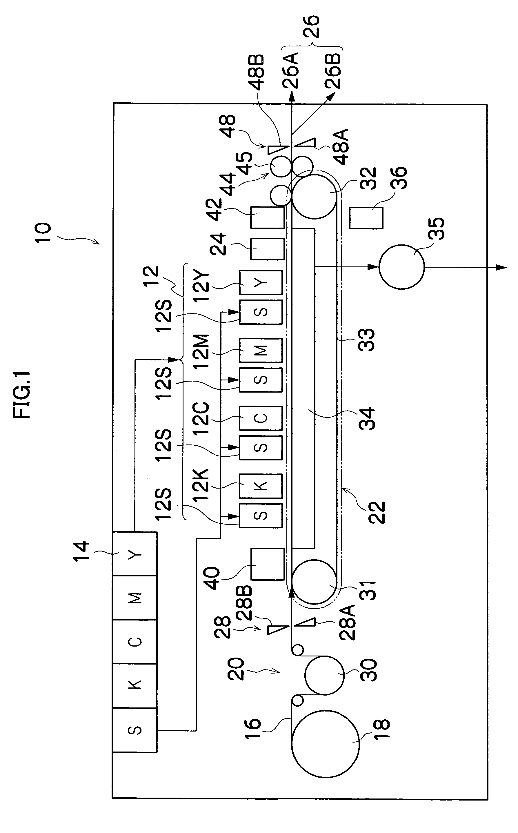
[0012] The present invention has been contrived in view of the foregoing circumstances, an object thereof being to provide an image forming apparatus and an image forming method whereby deposition interference between ink droplets, bleeding into the recording medium, and bleeding due to overlapping between ink droplets of different colors, and the like, can be prevented effectively by increasing the viscosity of the ink or solidifying (curing) the ink by means of a two-liquid reaction between the ink and a transparent treatment liquid.

Problems solved by technology

Here, deposition interference refers to shifting of the dot formation positions from the prescribed landing position (the position of the liquid droplet upon landing) and / or disturbance of the dot shapes, due to coalescence between mutually adjacent liquid droplets on the recording medium.
However, in the case of extremely simple judgment conditions of this kind, there is a problem in that suitable judgment cannot be made in order to prevent image deterioration caused by deposition interference, bleeding into ordinary paper, bleeding between colors, and the like.

Method used


Image

  • Image forming apparatus and image forming method
  • Image forming apparatus and image forming method
  • Image forming apparatus and image forming method

Examples


first embodiment

[0144]FIG. 12 shows a flowchart of a treatment liquid application control method relating to a

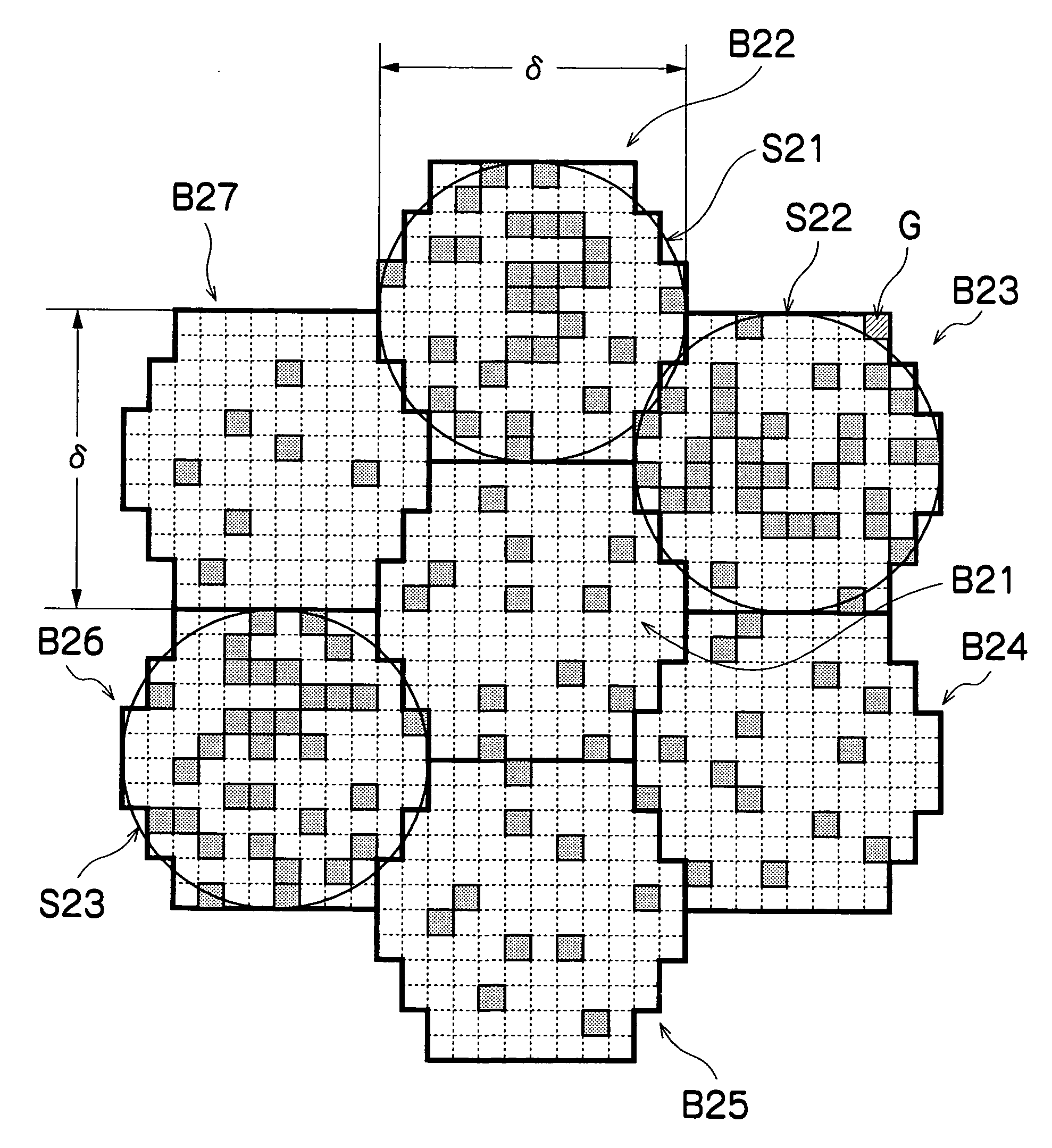
[0145] The description below follows the flowchart shown in FIG. 12. The processing shown in this flowchart is implemented principally by the evaluation value calculation device 94 and the treatment liquid application control device 96, following the processing performed by the image processing unit 90 and the block dividing device 92.

[0146] Firstly, at step S100, the dot deposition number counter C(k) for the block which is currently to be processed (the k-th block), is cleared to zero, and the j coordinate in the sub-scanning direction in the block is set to 0.

[0147] Next, at step S102, an initial value is substituted for the i coordinate in the main scanning direction in the j-th row in the sub-scanning direction (where, initially, j=0). In this case, if the blocks are square lattice-shaped blocks as shown in FIG. 8, then 0 is substituted for i, and if the blocks are other than square ...

second embodiment

[0159] Next, a treatment liquid application control method relating to the present invention will be described. In the present embodiment, when the dot deposition number is counted, weighting is given to cases where ink dots of the same color are mutually adjacent.

[0160]FIG. 13 shows a processing sequence of the present embodiment in the form of a flowchart, and below, this sequence is described with reference to the flowchart.

[0161] Firstly, at step S200, the dot deposition number counter C(k) and the j coordinate in the sub-scanning direction are respectively initialized (substituted with a value of 0), and at step S202, the i coordinate in the main scanning direction is initialized (in the case of a square lattice, it is set to 0; and in other cases, it is substituted with M(j)). Moreover, at step S204, the index clr indicating the ink color is initialized (substituted with a value of 0). Up to this point, the processing is similar to that of the first embodiment described above...

third embodiment

[0176] Next, a treatment liquid application control method relating to the present invention will be described. In the present embodiment, when the dot deposition number is counted, weighting is given to cases where ink dots of the different colors are mutually adjacent. Therefore, in the present embodiment, a counter, Count, for counting the number of dots of different colors to be deposited at the same position is introduced.

[0177] Below, the present embodiment is described with reference to the flowchart shown in FIG. 14.

[0178] Firstly, from step S300 until S304, the dot deposition number counter C(k), the j coordinate in the sub-scanning direction, the i coordinate in the main scanning direction, the ink color index clr, and the dot number counter, Count, for the dots of different colors to be deposited in the same pixel, are respectively initialized.

[0179] At step S306, it is judged whether or not an ink droplet of ink color clr is to be deposited onto the position (i, j), (i...


PUM


Abstract

The image forming apparatus comprises: an ink application device which applies ink to a recording medium; a treatment liquid application device which applies treatment liquid which causes the ink to increase in viscosity or solidify, by reacting with the ink; an image processing device which generates image data of multiple values from an input image; a block dividing device which divides an image region to be formed on the recording medium according to the image data into a plurality of blocks; an evaluation value calculation device which calculates an evaluation value for each of the blocks for judging an application of the treatment liquid to each of the blocks, according to the image data; and a treatment liquid application control device which controls a mode of applying the treatment liquid to each of the blocks, by comparing the evaluation value with a previously established threshold value.

Description

BACKGROUND OF THE INVENTION [0001] 1. Field of the Invention [0002] The present invention relates to an image forming apparatus and an image forming method, and more particularly, to technology for increasing the viscosity of ink or solidifying (curing) ink by means of a two-liquid reaction between ink and a transparent treatment liquid, and thereby preventing deposition interference between inks, bleeding into the recording medium, bleeding due to overlapping of ink droplets of different colors, and the like. [0003] 2. Description of the Related Art [0004] Inkjet recording apparatuses (inkjet printers) having an inkjet head (ink ejection head) in which a plurality of nozzles are arranged, are known as image forming apparatuses. An inkjet recording apparatus of this kind forms images by forming dots on a recording medium, by ejecting ink as droplets from nozzles, while causing the inkjet head and the recording medium to move relatively to each other. [0005] Various methods are known...

Claims


Application Information

Patent Timeline
Patent Type & Authority Applications(United States)
IPC IPC(8): B41J2/17
CPCB41J2/2114
Inventor YAMANOBE, JUN
Owner FUJIFILM CORP
Learn More