Vehicle peripheral visual confirmation apparatus

Inactive Publication Date: 2006-04-06
AUTONETWORKS TECH LTD +2
View PDF5 Cites 26 Cited by
  • Summary
  • Abstract
  • Description
  • Claims
  • Application Information

AI Technical Summary

Benefits of technology

[0017] According to the above-aspects of the invention, when the display controller cuts out a part of the image picked up by the camera, the display controller synthesizes an image showing the

Problems solved by technology

However, when the range of the visual field of the camera 3 is widened by the fisheye lens or the like, even if the picked up image is directly displayed on the display devi

Method used


Image

  • Vehicle peripheral visual confirmation apparatus
  • Vehicle peripheral visual confirmation apparatus
  • Vehicle peripheral visual confirmation apparatus

Examples


Embodiment Construction

[0038] Firstly, a principle of a visually recognizing device for a periphery of a vehicle according to one embodiment of the present invention will be described.

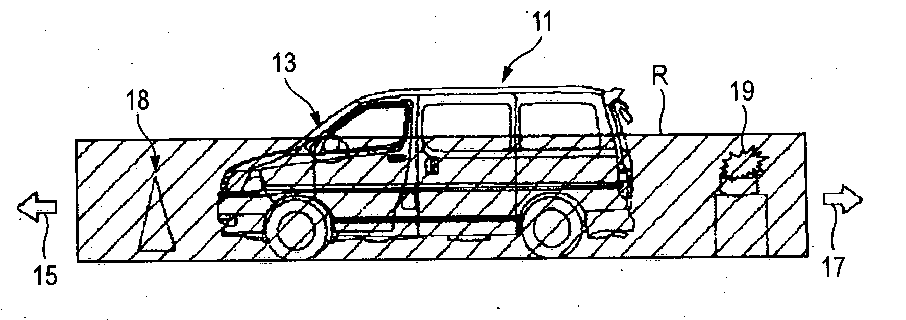
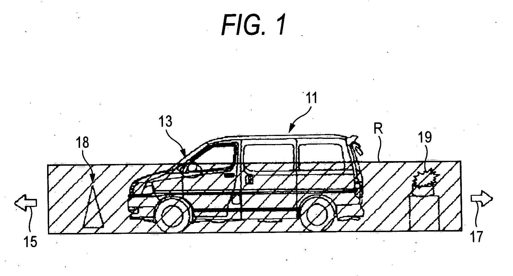
[0039] A vehicle peripheral visual confirmation apparatus picks up by a camera 13 installed on, for instance, a left side surface of a vehicle 11, the image of a scene having a prescribed wide range R of a visual field including both a front part 15 and a rear part 17 viewed from a position where the camera 13 is installed, as shown in FIGS. 1 and 2. Then, the apparatus displays obstacles 18 and 19 both in the front and rear parts of the vehicle included in the picked up image on a display device in the vehicle. Thus, a driver can easily visually recognize the obstacles 18 and 19 or a guide line (white line) 20 drawn on a road.

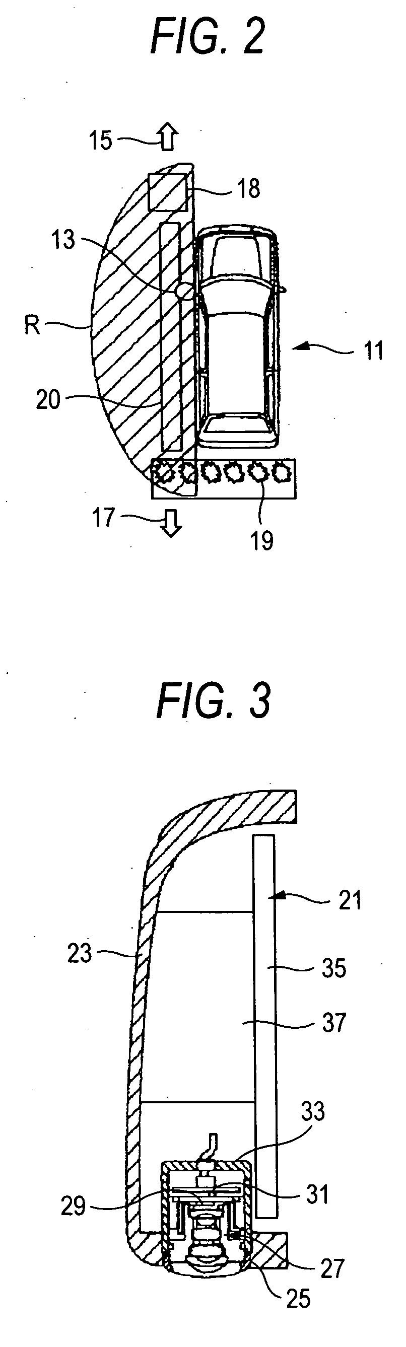
[0040] Here, as shown in FIG. 3, the camera 13 is fitted to an installing hole 25 formed in the lower end part of a casing member 23 of a door mirror 21 to pick up an image about a lower part of the ...


PUM


Abstract

A camera taking an image in a wide range of a visual field cuts out, an image of a vehicle's rear part of the image picked up by the camera. The camera rotates or inverts the image and adjusts the image in the direction corresponding to a mirror image of a door mirror. The rearward image that can be sensitively, easily and visually recognized by a driver can be provided. A forward image or the sideward image is properly switched as required. When a part of the image picked up by the camera is cut out, images showing the range of the visual field of the cut out image are synthesized and displayed in a display device.

Description

BACKGROUND OF THE INVENTION [0001] 1. Field of the Invention [0002] The present invention relates to a vehicle peripheral visual confirmation apparatus by which a driver visually recognizes a vehicle peripheral that cannot visually recognized from a driver's seat of vehicle. [0003] 2. Description of the Related Art [0004] When the driver visually recognizes the position that is not open to the eye of the driver in the driver's seat of the vehicle, the images of prescribed directions in the periphery of the vehicle have been hitherto picked up by a camera provided in the vehicle and the picked-up images have been displayed on a display device disposed in the vehicle. [0005] For instance, in the case of a vehicle 1 having a right handle, a camera 3 has been ordinarily disposed only in a left side as shown in FIG. 20, the image of a scene located in a prescribed range 4 of the left side of the vehicle 1 including the front wheel of the vehicle has been usually picked up by the camera 3...

Claims


Application Information

Patent Timeline
IPC IPC(8): H04N7/18B60Q1/00G08G1/14
CPCB60R1/00B60R2300/30B60R2300/404B60R2300/802B60R2300/8066H04N5/2251H04N5/23238H04N23/698H04N23/63
Inventor OKADA, JUN
Owner AUTONETWORKS TECH LTD
Why Eureka
Try Eureka