System and method for power conversion

a power conversion and power converter technology, applied in the direction of power conversion systems, dc-dc conversion, instruments, etc., can solve the problems of reducing the power factor of the overall system, bulky power converter systems, and reducing the overall efficiency of the system

Inactive Publication Date: 2006-04-06
GENERAL ELECCRTIC
View PDF39 Cites 27 Cited by
  • Summary
  • Abstract
  • Description
  • Claims
  • Application Information

AI Technical Summary

Problems solved by technology

However, current power converter systems generally inject harmonics into the system and into the electrical distribution grid, and also reduce the power factor of the overall system.
However, this makes the power converter system bulky and reduces the overall efficiency of the system.

Method used


Image

  • System and method for power conversion
  • System and method for power conversion
  • System and method for power conversion

Examples


Embodiment Construction

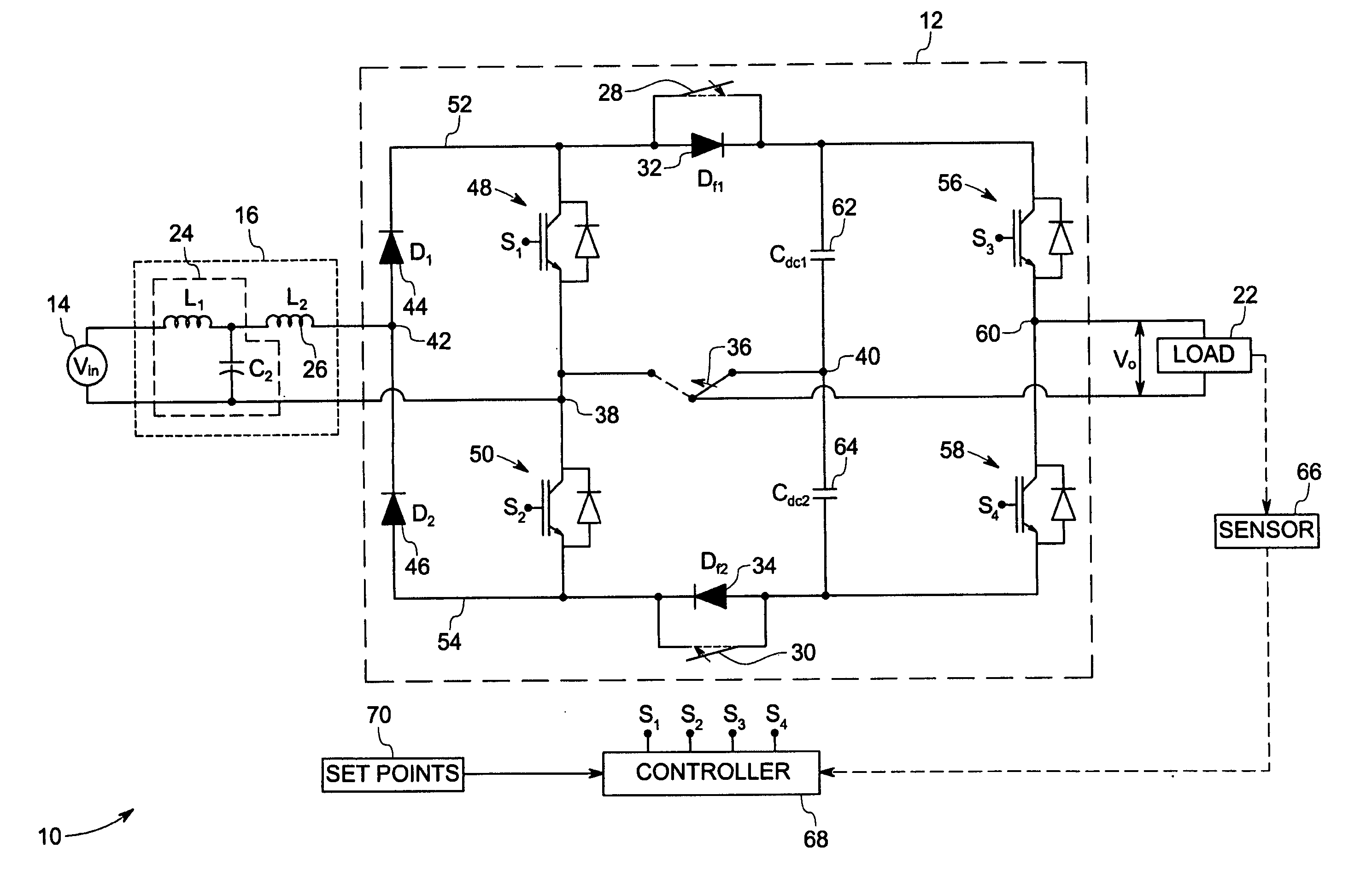
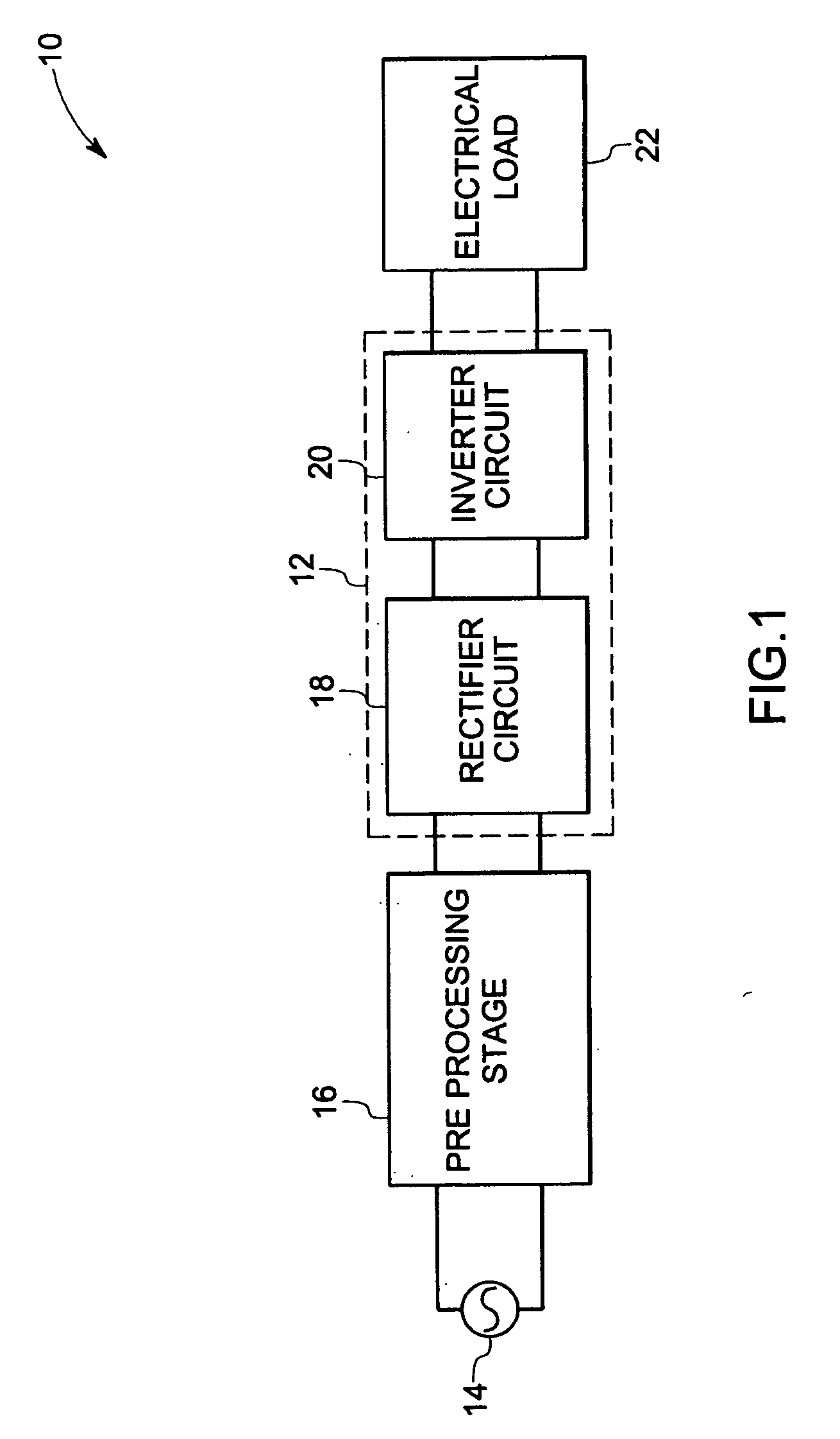
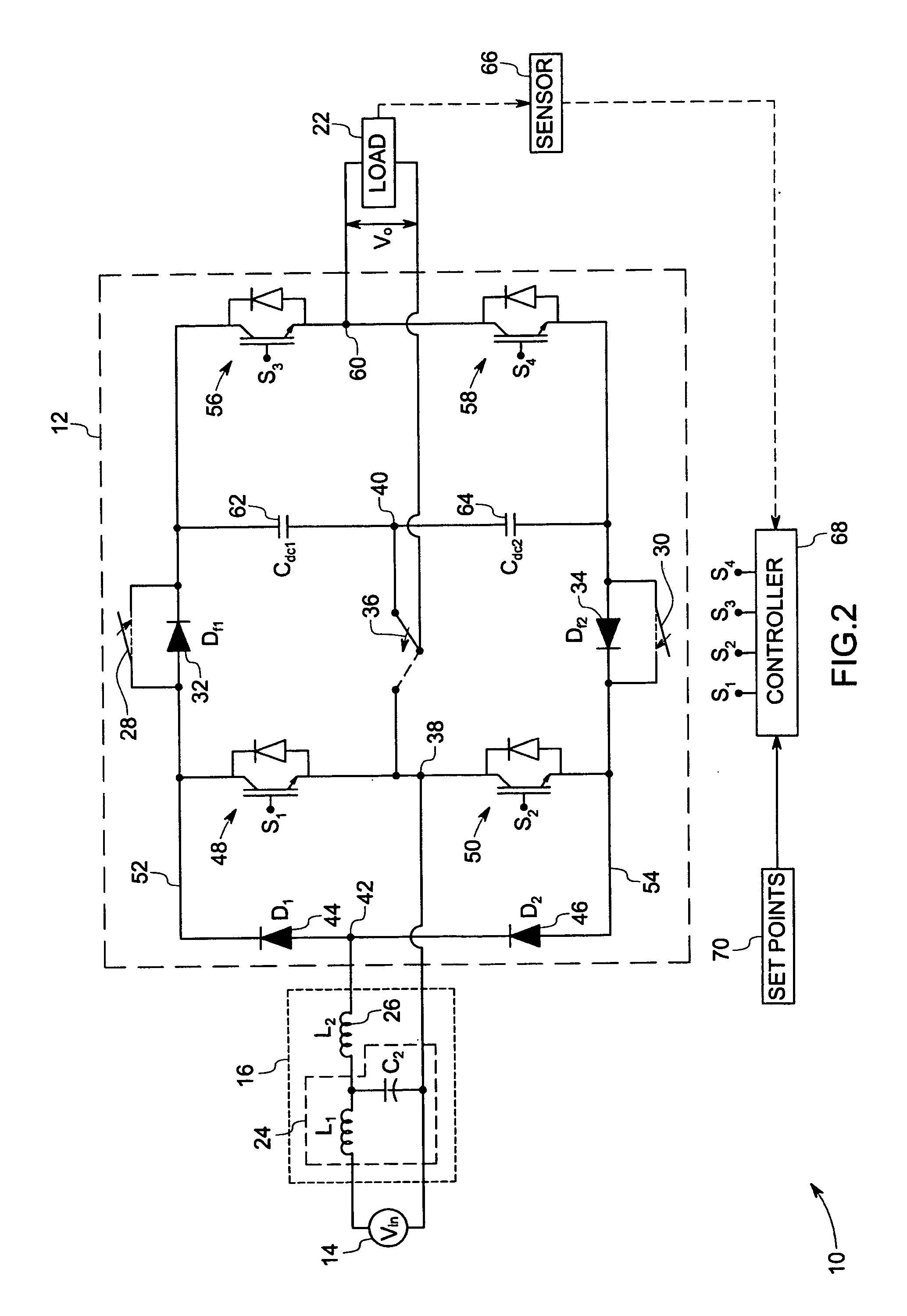
[0016]FIG. 1 is a block diagram of an ac-ac power converter system 10 implemented according to one aspect of the invention. The ac-ac power converter system 10 includes a power processing stage or an ac-ac power converter 12 for converting an input ac power to a desired output ac power. The ac-ac power converter 12 receives single-phase ac power from a single-phase ac power source 14, which may be ac power mains, via a pre power processing stage 16. The pre processing stage 16 prevents or reduces harmonics generated by the ac-ac power converter 12 from being injected into the ac power source 14.

[0017] The ac-ac power converter 12 further includes a rectifier circuit 18 for converting the input ac power to a dc power, and an inverter circuit 20 for converting the dc power from the rectifier circuit into the desired output ac power. The output ac power from the inverter circuit 20 is fed to an electrical load 22 coupled to the ac-ac power converter 12. In the illustrated embodiment, ...


PUM


Abstract

An ac-ac power converter system is provided for supplying power to an electrical load. The ac-ac power converter system provides an output voltage having variable amplitude and/or frequency. The ac-ac power converter system includes a boost inductor for applying a discontinuous current to an ac-ac power converter. The ac-ac power converter includes a rectifier circuit comprising of a first set of gate controllable active switches for converting an input ac power to a dc power and an inverter circuit comprising of a second set of gate controllable active switches for converting the dc power to an output ac power. In addition, the ac-ac power converter system includes a switch for switching between a first mode of operation and a second mode of operation. The first set of gate controllable active switches is common between the inverter circuit and the rectifier circuit and is operable at about 50 percent of duty cycle in the first mode of operation while the inverter circuit is a half bridge inverter circuit in the second mode of operation.

Description

BACKGROUND [0001] The invention relates generally to electrical power conversion systems, and more particularly to control of electrical machines via ac-ac power converter systems. [0002] A range of applications exists for power conversion circuitry, particularly for the control of electrical machines, such as motors. A wide variety of applications, such as air conditioners, blowers and others utilize electrical machines operating at different speeds. These different speeds may be obtained by varying amplitude and / or frequency of the voltage applied to the electrical machine. The amplitude and / or frequency of the voltage applied to the electrical machine can be varied with the help of a power processing stage introduced between the electrical machine and the supply voltage. [0003] For example, power converter systems of various topologies may be employed to achieve speed control of electrical machines via the techniques mentioned above. However, current power converter systems gener...

Claims


Application Information

Patent Timeline
Patent Type & Authority Applications(United States)
IPC IPC(8): H02M3/335
CPCH02M5/4585H02M1/0085
Inventor MHASKAR, UDAY PRAKASHRAOWIEGMAN, HERMAN LUCAS NORBERTSANGLIKAR, AMIT RAJAPHANSALKAR, BANSIDHAR JAGANNATHWRIGHT, KAMRON MARK
Owner GENERAL ELECCRTIC
Why Eureka
Try Eureka