Switching-mode power supply having a synchronous rectifier

a technology of synchronous rectifier and power supply, which is applied in the direction of dc-dc conversion, power conversion systems, climate sustainability, etc., can solve the problems of noise production, difficulty in exact synchronization of turning on undesired overlapping of the conducting period of the active switch and the synchronous rectifier switch, etc., to achieve the effect of enhancing efficiency and reducing power loss

Inactive Publication Date: 2007-08-28
SANKEN ELECTRIC CO LTD
View PDF8 Cites 25 Cited by
  • Summary
  • Abstract
  • Description
  • Claims
  • Application Information

AI Technical Summary

Benefits of technology

[0035]The present invention is perhaps best characterized by the synchronous rectifier control circuit which comprises, for determination of the conducting periods of the synchronous rectifier switch: (a) the synchronous rectification period determination capacitor for providing a voltage for determination of periods of time during which the synchronous rectifier switch is to conduct; (b) the first current source connected to the synchronous rectification period determination capacitor for charging the same with a current corresponding to a voltage across the inductance means during the conducting periods of the active switch; and (c) the second current source connected to the synchronous rectification period determination capacitor for permitting the flow of a discharge current corresponding to the DC output voltage. The charge and discharge periods of the synchronous rectification period determination capacitor are therefore accurately determinable in agreement with the energy storage and release periods of the inductance means due to the on / off operation of the active switch. The synchronous rectifier switch may thus be held on during optimal periods of time for enhancement of efficiency as the conducting periods of the synchronous rectifier switch substantially agree with the energy release periods of the inductance means. There will be practically no risk of noise production or circuit destruction due to the concurrent conduction of the synchronous rectifier switch and active switch.
[0039]In a further preferred embodiment of the invention the synchronous rectification period determination capacitor is positively prevented from discharge during the conducting periods of the active switch.
[0041]In a further preferred embodiment of the invention the synchronous rectifier switch control pulse forming circuit is simplified in construction.
[0046]In a further preferred embodiment of the invention the synchronous rectifier switch is not driven under light loading, thereby eliminating power loss from the driving of this switch and enhancing efficiency under light loading.

Problems solved by technology

One of them is the difficulty of turning on the synchronous rectifier switch in exact synchronism with the conducting periods of the rectifying diode, these conducting periods being subject to change with the input voltage and with the loading.
Another weakness manifested itself in the event of an abrupt drop in the output voltage of the switching-mode power supply in response to a change in loading.
The possible result was the undesired overlapping of the conducting periods of the active switch and those of the synchronous rectifier switch.
Such overlapping, if it occurred at all, might lead to noise production and, worse yet, to the destruction of the associated circuit parts.
The yet-unremedied drawbacks of the synchronous rectification technology discussed above are not peculiar to the flyback DC-to-DC converter.

Method used


Image

  • Switching-mode power supply having a synchronous rectifier
  • Switching-mode power supply having a synchronous rectifier
  • Switching-mode power supply having a synchronous rectifier

Examples


first embodiment

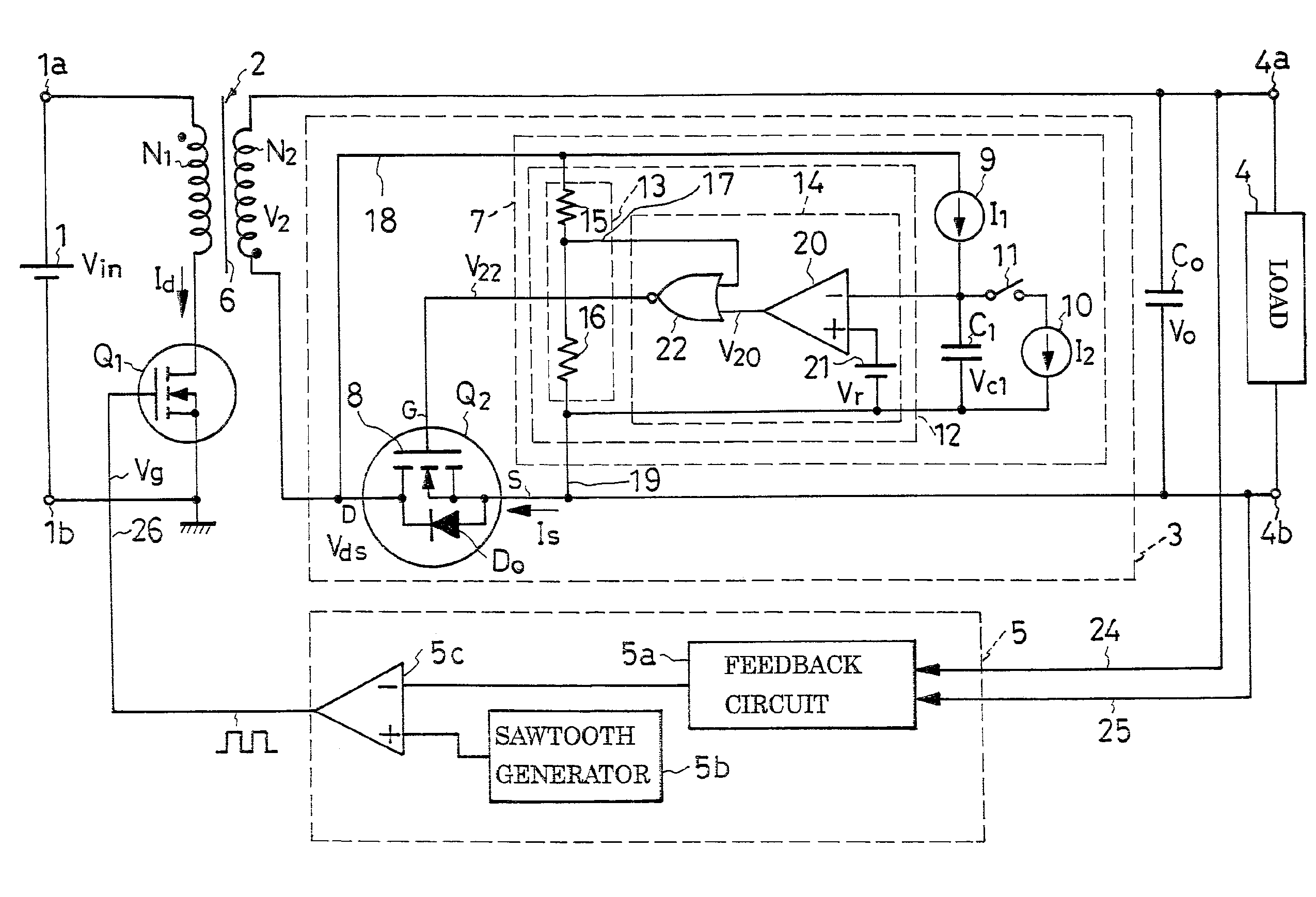
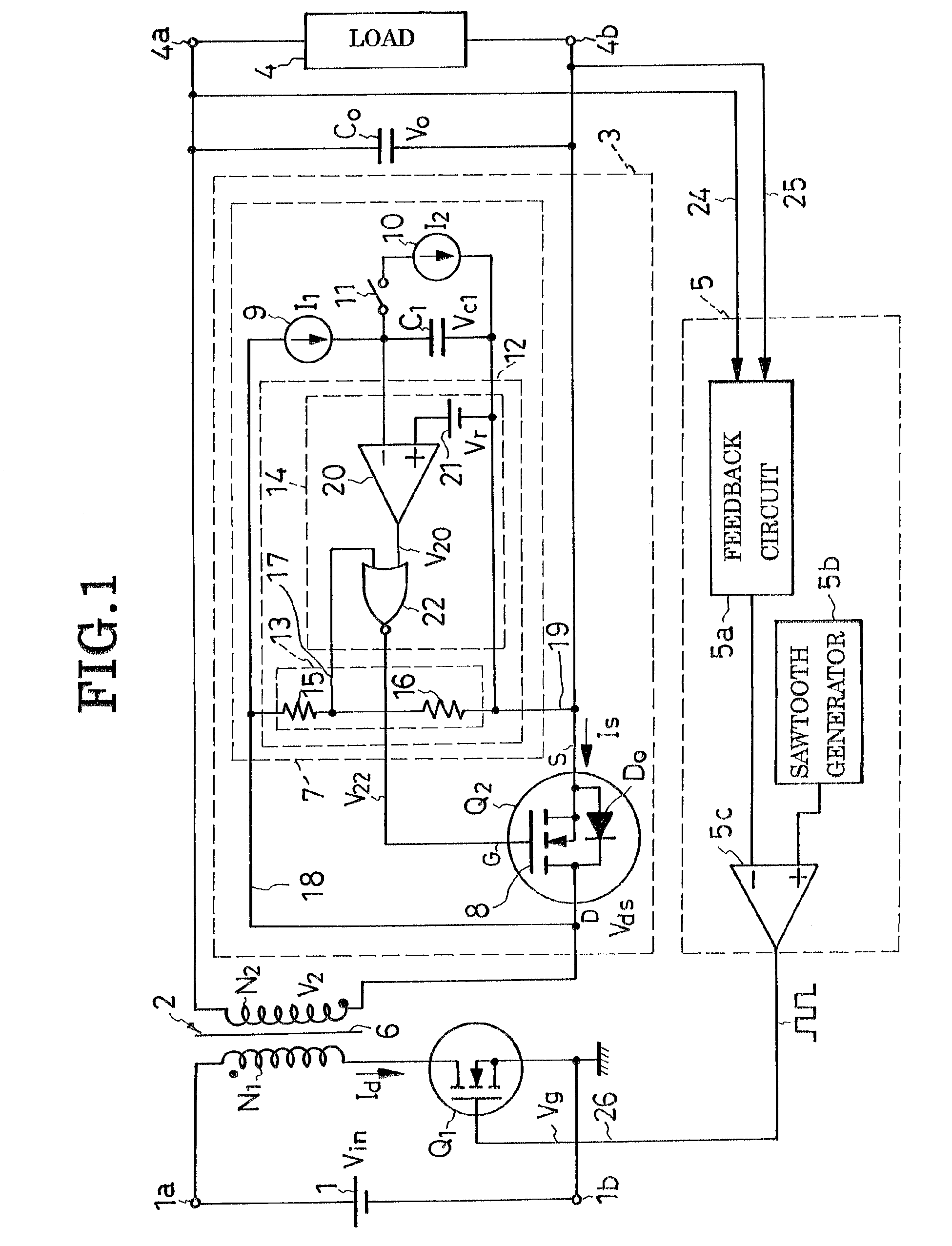
[0063]The present invention is currently believed to be best embodied in the switching-mode power supply of flyback DC-to-DC converter type diagramed in its entirety in FIG. 1 of the above drawings. Reference will also be had to FIGS. 2 and 3 in the course of the following explanation of this first embodiment of the invention. With reference first to FIG. 1 the exemplified flyback DC-to-DC power supply broadly comprises:

[0064]1. A pair of DC input terminals 1a and 1b as DC input means shown coupled to a source 1 of DC voltage for providing a DC input voltage Vin.

[0065]2. An inductance means herein shown as a transformer 2.

[0066]3. An active switch Q1 as switching means for rapidly switching the DC input voltage Vin on and off.

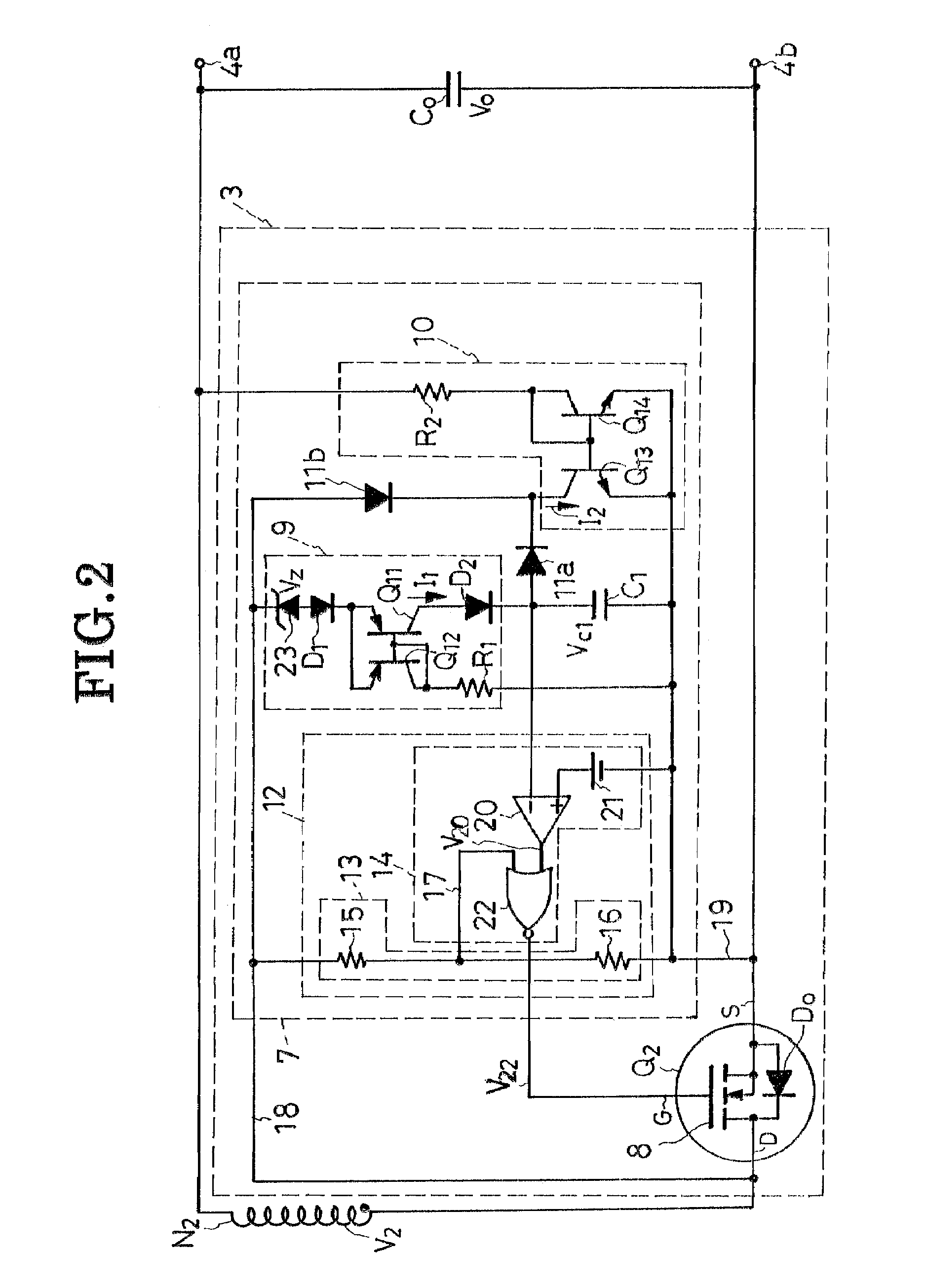
[0067]4. A synchronous rectifier circuit 3, to which the present invention particularly pertains, on the output side of the transformer 2.

[0068]5. A smoothing capacitor Co.

[0069]6. A pair of DC output terminals 4a and 4b as DC output means shown connected to a ...

embodiment

of FIG. 4

[0138]Shown in this figure is a modified synchronous rectifier circuit 3a which lends itself to use in the switching-mode power supply of FIGS. 1 and 2 in substitution for the first disclosed synchronous rectifier circuit 3 shown in detail in FIG. 2. The modified synchronous rectifier circuit 3a is itself akin to its FIG. 2 counterpart 3 except for a synchronous rectifier control circuit 7a, which in turn is similar to its FIG. 2 counterpart 7 except for modifications in a first current source 9a. Thus an explanation of the modified first current source 9a and of its operation will suffice for full disclosure of this second embodiment.

[0139]The modified first current source 9a of the synchronous rectifier control circuit 7a differs from its FIG. 2 counterpart 9 in having no zener diode and in having the first collector resistor R1 connected between the collector of the second transistor Q12 and the transformer secondary N2. So modified, the first current source 9a functions...


PUM


Abstract

A switching-mode power supply capable of causing conduction through a synchronous rectifier switch exactly when required. Included is a transformer having a primary winding connected to a pair of DC input terminals via an active switch, and a secondary winding connected to a pair of DC output terminals via a synchronous rectifier and a smoothing capacitor. The synchronous rectifier is a parallel connection of a synchronous rectifier switch and a diode. In order to cause conduction through the synchronous rectifier switch while the diode is conducting, there is provided a synchronous rectifier control circuit comprising two current sources, a conduction period determination circuit, and a synchronous rectifier switch control pulse forming circuit.

Description

CROSS REFERENCE TO RELATED APPLICATIONS[0001]This is a continuation of Application PCT / JP2005 / 011985, filed Jun. 29, 2005, which claims priority to Japanese Patent Application No. 2004-196685 filed Jul. 2, 2004.BACKGROUND OF THE INVENTION[0002]This invention relates to an electronic power supply unit known as the switching-mode power supply, and more specifically, to such a power supply of the kind having a synchronous rectifier circuit.[0003]A typical conventional switching-mode power supply with a flyback DC-to-DC converter includes a transformer having a primary winding coupled to the pair of DC input terminals via an active switch, and a secondary winding coupled to the pair of DC output terminals via a rectifying diode and smoothing capacitor. The DC input voltage is rapidly turned on and off as the active switch is driven by pulses that have been width-modulated by a feedback circuit monitoring the DC output voltage. Energy is stored on the transformer during the conducting pe...

Claims


Application Information

Patent Timeline
Patent Type & Authority Patents(United States)
IPC IPC(8): H02M3/335H02M7/217
CPCH02M3/33592Y02B70/1475Y02B70/10
Inventor KYONO, YOICHI
Owner SANKEN ELECTRIC CO LTD
Why Eureka
Try Eureka