Detector array using internalized light sharing and air coupling

a technology of light sharing and detector array, applied in the direction of instruments, radiation measurement, measurement devices, etc., can solve the problem of complicated fabrication of the entire detector, and achieve the effect of high packing fraction, accurate determinability, and high efficiency

Inactive Publication Date: 2006-03-28
SIEMENS MEDICAL SOLUTIONS USA INC
View PDF13 Cites 29 Cited by
  • Summary
  • Abstract
  • Description
  • Claims
  • Application Information

AI Technical Summary

Benefits of technology

[0014]The present invention is a detector array for use in imaging applications such as X-ray imaging, fluoroscopy, positron emission tomography (PET), single photon emission computed tomography (SPECT), computed tomography (CT), gamma camera and digital mammography systems. The detector array of the present invention includes a plurality of scintillators for use in association with an imaging device. The array is fabricated such that the location of the impingement of radiation upon an individual scintillator detector is accurately determinable. This method allows an efficient, consistent, accurate, and cost-effective process for creating an array with high packing fraction, high light output, and high sensitivity. This method introduces internalized reflective light partitions between the scintillator elements themselves thereby eliminating the need for cuts in the attached light guide. Therefore, a continuous light guide may be used in conjunction with this array, simplifying the entire detector array fabrication process.

Problems solved by technology

This additionally complicates the fabrication of the entire detector.

Method used


Image

  • Detector array using internalized light sharing and air coupling
  • Detector array using internalized light sharing and air coupling
  • Detector array using internalized light sharing and air coupling

Examples


Embodiment Construction

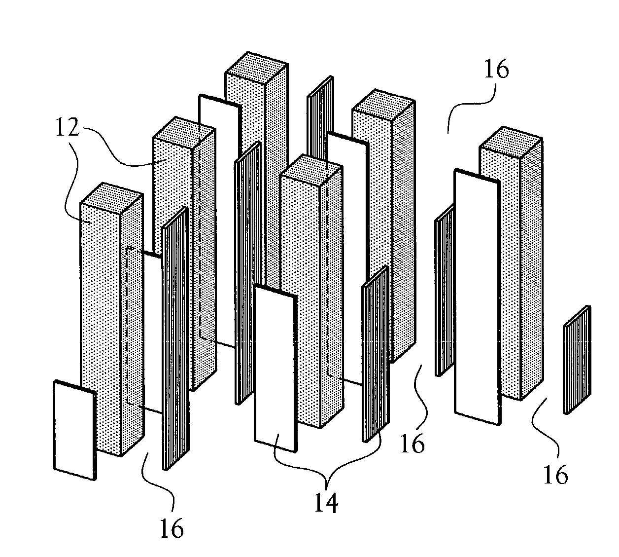
[0030]A detector array for use in imaging applications such as X-ray imaging, fluoroscopy, positron emission tomography (PET), single photon emission computed tomography (SPECT), computed tomography (CT), gamma camera and digital mammography systems is provided. The detector array is illustrated at 10 in the figures. The detector array, or array 10, includes a plurality of scintillator elements 12 for use in association with an imaging device (not illustrated). The array 10 is fabricated such that location of the impingement of radiation upon an individual scintillator element 12 is accurately determinable. The present invention provides for the creation of a highly packed, high light output, high sensitivity, scintillator array 10 in an efficient, consistent, accurate and cost-effective manner.

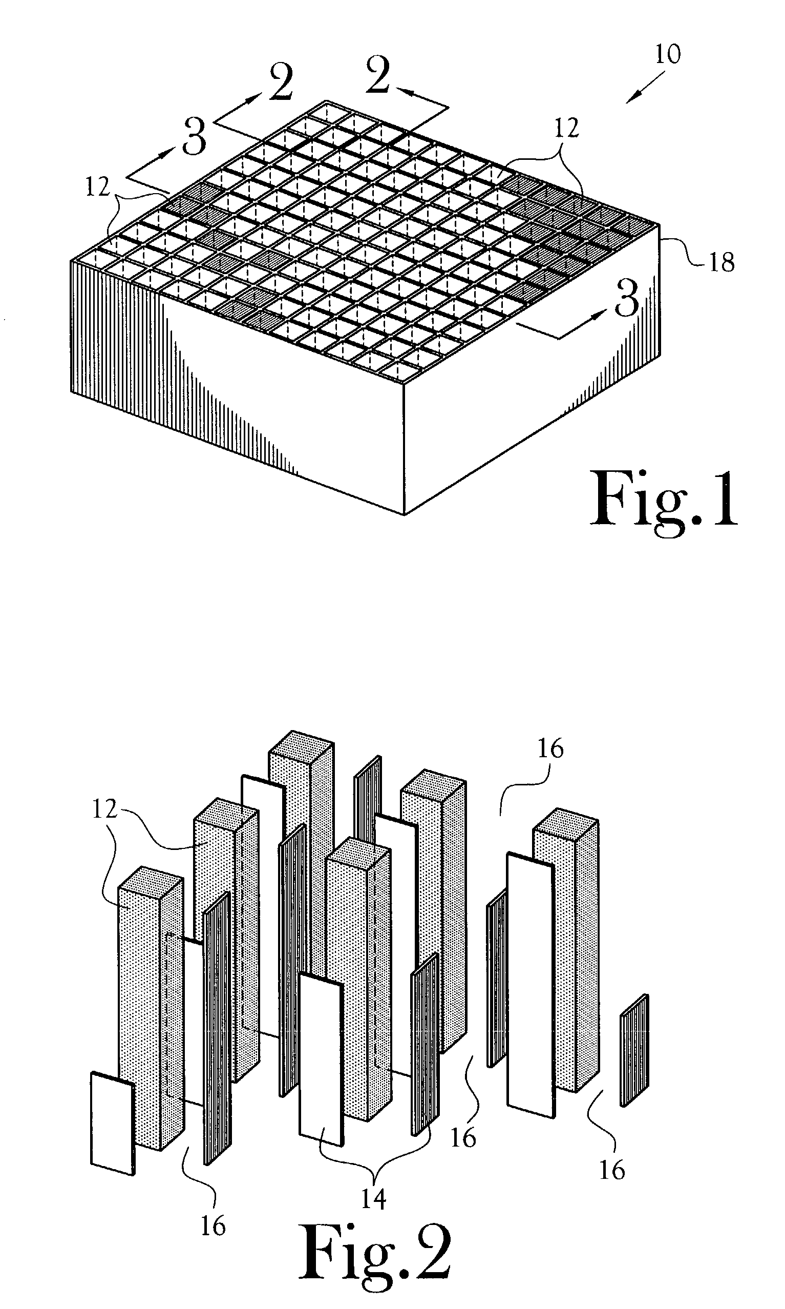
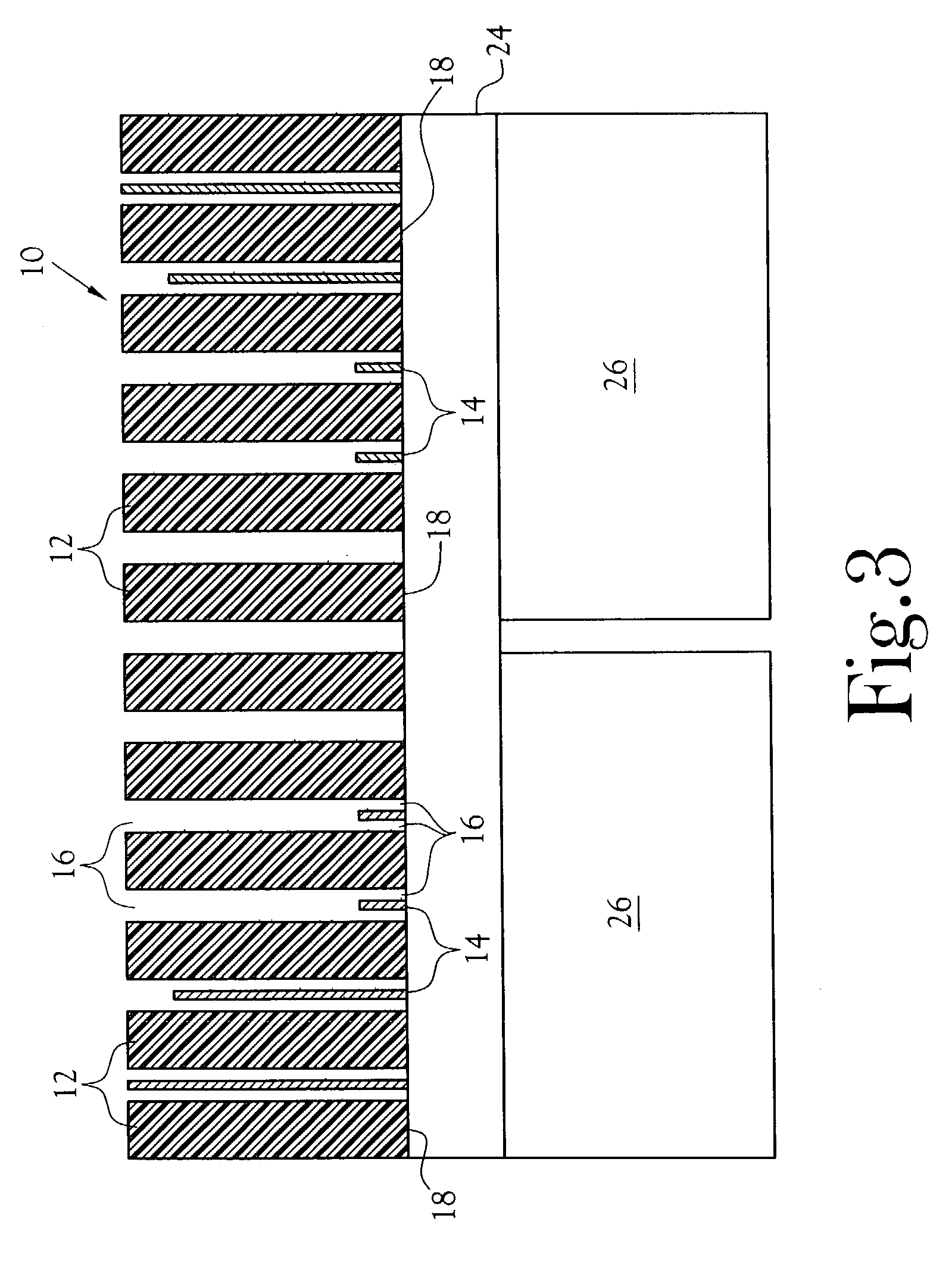
[0031]As best illustrated in FIG. 1, the array 10 defines an M×N array of scintillator elements 12. In the illustrated embodiment, the array 10 defines a 12×12 matrix of scintillator elements...


PUM


Abstract

A method for fabricating an array adapted to receive a plurality of scintillators for use in association with an imaging device. The method allows the creation of a detector array such that location of the impingement of radiation upon an individual scintillator detector is accurately determinable. The array incorporates an air gap between all the scintillator elements. Certain scintillators may have varying height reflective light partitions to control the amount of light sharing which occurs between elements. Light transmission is additionally optimized by varying the optical transmission properties of the reflective light partition, such as by varying the thickness and optical density of the light partitions. In certain locations, no light partitions exist, thereby defining an air gap between those elements. The air gap allows a large increase in the packing fraction and therefore the overall sensitivity of the array.

Description

CROSS-REFERENCE TO RELATED APPLICATIONS[0001]Not ApplicableSTATEMENT REGARDING FEDERALLY SPONSORED RESEARCH OR DEVELOPMENT[0002]Not ApplicableBACKGROUND OF THE INVENTION[0003]1. Field of Invention[0004]This invention pertains to a method for fabricating a detector array for use in imaging applications such as X-ray imaging, fluoroscopy, positron emission tomography (PET), single photon emission computed tomography (SPECT), computed tomography (CT), gamma camera and digital mammography systems. More particularly, the present invention provides a simple approach for fabricating a detector array with high packing fraction resulting in greater sensitivity while still maintaining spatial resolution.[0005]2. Description of the Related Art[0006]In the field of imaging, it is well known that imaging devices incorporate a plurality of scintillator arrays for detecting radioactivity from various sources. It is also common practice, when constructing scintillator arrays composed of discrete sc...

Claims


Application Information

Patent Timeline
Patent Type & Authority Patents(United States)
IPC IPC(8): G01T1/202G01T1/20
CPCG01T1/202G01T1/2002B33Y80/00
Inventor AYKAC, MEHMETSCHMAND, MATTHIAS J.DOSHI, NIRAJ K.WILLIAMS, CHARLES W.NUTT, RONALD
Owner SIEMENS MEDICAL SOLUTIONS USA INC
Why Eureka
Try Eureka