Eureka AIR delivers breakthrough ideas for toughest innovation challenges, trusted by R&D personnel around the world.

Device and method for intra-bronchial provision of a therapeutic agent

a technology of intrabronchial bronchial tube and therapeutic agent, which is applied in the direction of catheters, prostheses, therapy, etc., to achieve the effect of limiting mucociliary transport, inhibiting movement, and inhibiting therapeutic agent movemen

Inactive Publication Date: 2006-04-06
GYRUS ACMI INC (D B A OLYMPUS SURGICAL TECH AMERICA)
View PDF99 Cites 22 Cited by
  • Summary
  • Abstract
  • Description
  • Claims
  • Application Information

AI Technical Summary

Benefits of technology

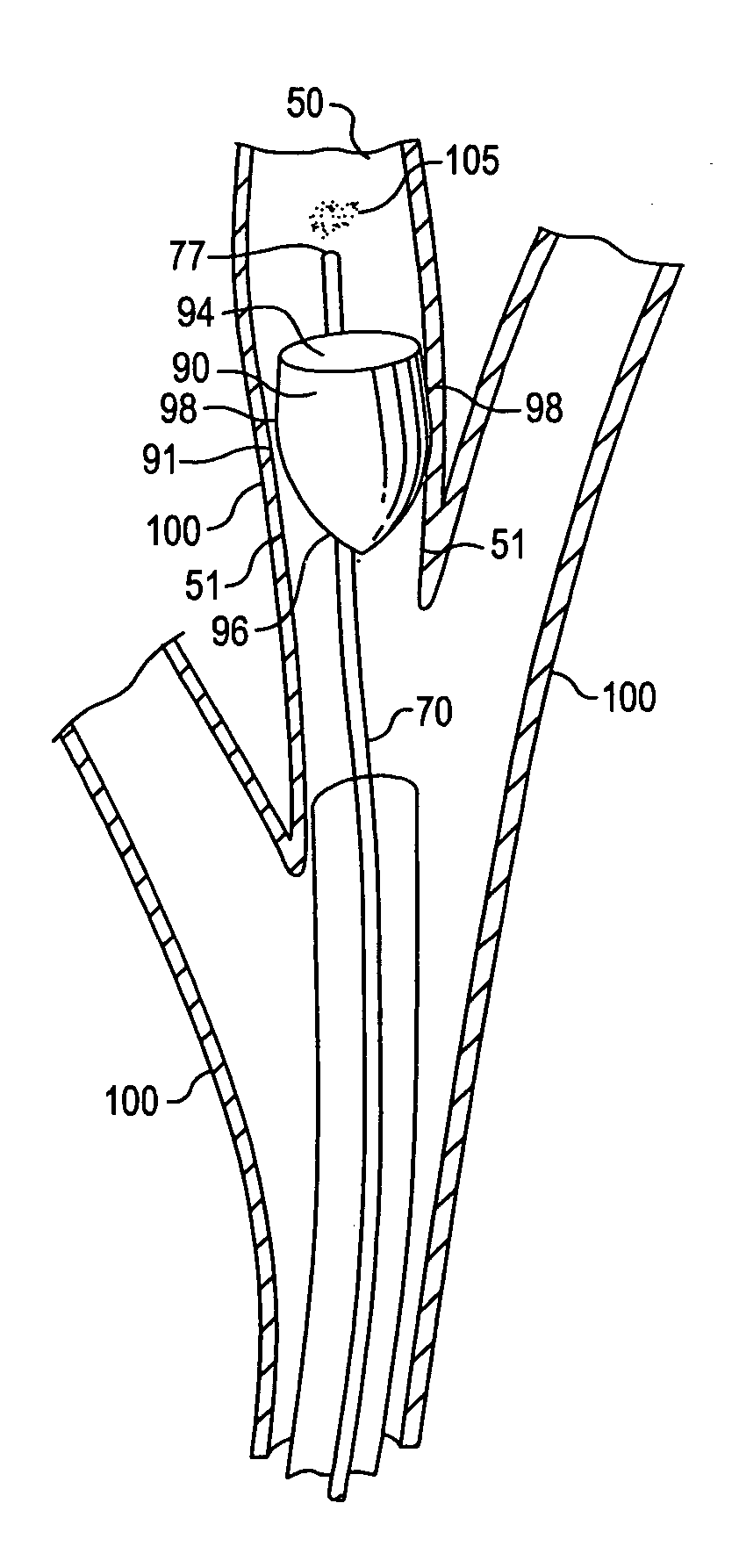
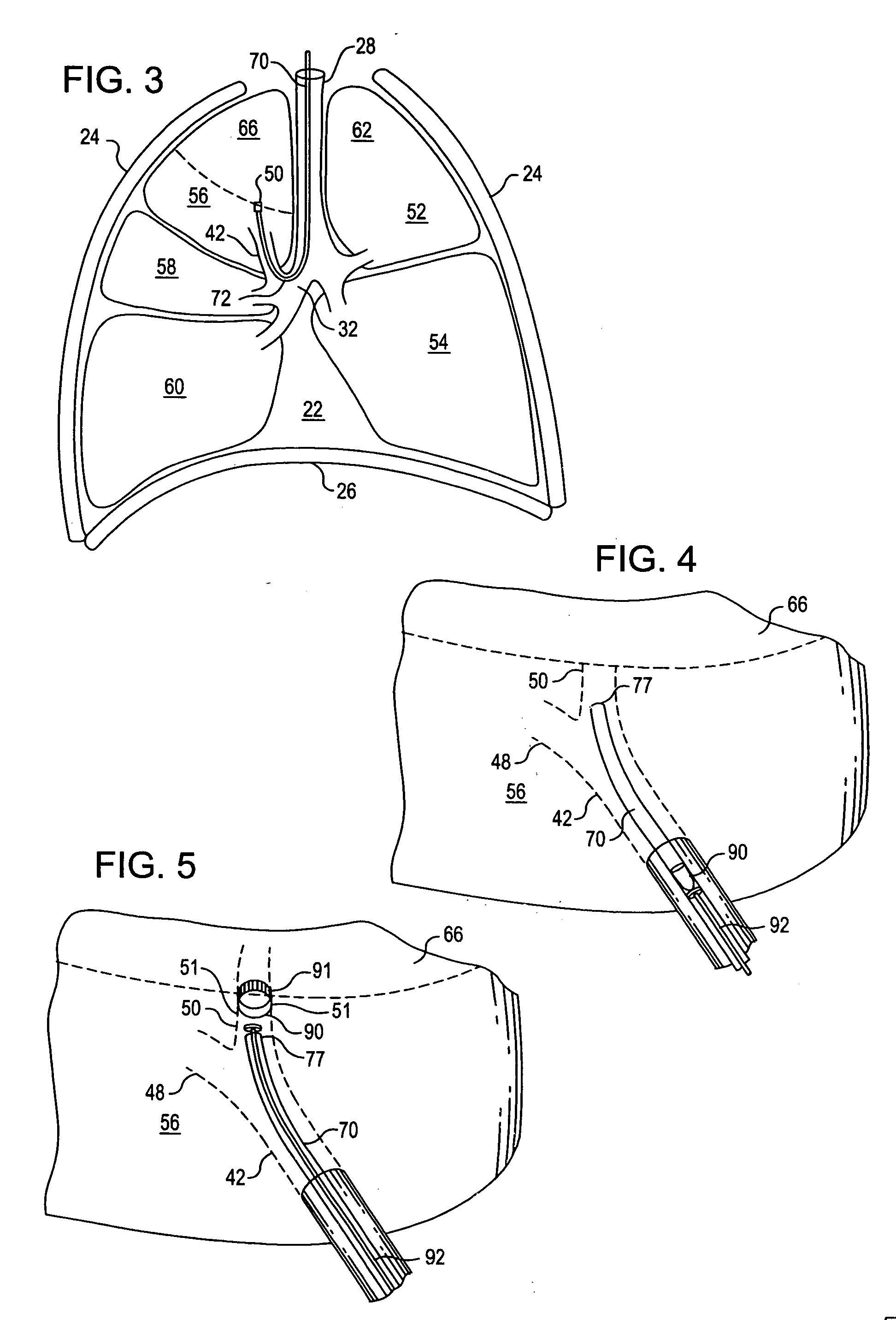
[0009] The invention further provides an intra-bronchial device for maintaining a therapeutic agent within an air passageway. The device includes a flow control member arranged for placement in the air passageway and inhibiting the therapeutic agent from moving proximal of the control member, and the therapeutic agent. The control member may inhibit movement of the therapeutic agent by limiting flow from the air passageway. The control member may inhibit movement of the therapeutic agent by limiting flow into the air passageway, which limitation may be by limiting mucociliary transport from the air passageway. The control member may include a one-way valve. The one-way valve may permit inhalation of air into the air passageway, or permit exhalation of air from the air passageway. The control member may include a flexible membrane impervious to air flow. The flexible membrane may be arranged in cooperation with a wall of the air passageway to form a one-way valve permitting airflow from the air passageway, or a one-way valve permitting airflow into the air passageway. The control member may include a separator arranged to inhibit the movement of the therapeutic agent while allowing movement of air. The molecules of the therapeutic agent may be associated with molecules larger than air molecules, and the separator arranged to inhibit movement of the associated molecules while allowing movement of air molecules. The control member may include a semi-permeable membrane arranged to retain the therapeutic agent distal of the control member while permitting air and water molecules to be exhaled. The control member may limit airflow from the air passageway sufficiently to maintain inflation of a lung portion communicating with the air passageway. The control member may allow airflow from the air passageway sufficiently to prevent over-inflation of the lung portion. The control member may further include at least one anchor that retains the intra-bronchial device within the air passageway when the anchor is deployed, and at least one anchor may be releasable from the air passageway for removal of the intra-bronchial device. The control member may be further arranged to automatically terminate the inhibiting of movement by the therapeutic agent. The automatic termination may be provided by deterioration of the control member, or by dissolution of the control member.

Problems solved by technology

The control member may inhibit movement of the therapeutic agent by limiting flow into the air passageway, which limitation may be by limiting mucociliary transport from the air passageway.

Method used


Image

  • Device and method for intra-bronchial provision of a therapeutic agent
  • Device and method for intra-bronchial provision of a therapeutic agent
  • Device and method for intra-bronchial provision of a therapeutic agent

Examples


Embodiment Construction

[0033] In the following detailed description of exemplary embodiments of the invention, reference is made to the accompanying drawings that form a part hereof. The detailed description and the drawings illustrate specific exemplary embodiments by which the invention may be practiced. These embodiments are described in sufficient detail to enable those skilled in the art to practice the invention. It is understood that other embodiments may be utilized, and other changes may be made, without departing from the spirit or scope of the present invention. The following detailed description is therefore not to be taken in a limiting sense, and the scope of the present invention is defined by the appended claims.

[0034] Throughout the specification and claims, the following terms take the meanings explicitly associated herein unless the context clearly dictates otherwise. The meaning of “a”, “an”, and “the” include plural references. The meaning of “in” includes “in” and “on.” Referring to...


PUM


Abstract

The present invention includes an intra-bronchial device, system, and method for providing a therapeutic agent to a patient. A device includes a flow control member for placement in an air passageway communicating with a lung portion, and when deployed in the air passageway inhibits a therapeutic agent distal of the control member from moving proximal of the control member, and includes the therapeutic agent associated with the flow control member. The control member may inhibit movement of the therapeutic agent by limiting airflow, and may include a one-way valve limiting exhalation of air from the lung portion. The control member may include a flexible membrane impervious to air flow, or a separator arranged to inhibit the movement of the therapeutic agent. The control member may include at least one anchor, and the anchor may be releasable from the air passageway for removal of the intra-bronchial device.

Description

RELATED APPLICATION [0001] This application is a continuation-in-part of and claims priority based on U.S. applications entitled INTRA-BRONCHIAL AIRFLOW CONTROL DEVICE THAT CONTROLS BIOLOGICAL INTERACTION WITH THE PATIENT filed Feb. 21, 2002, application Ser. No. 10 / 081,712; and INTRA-BRONCHIAL AIRFLOW CONTROL DEVICE THAT CONTROLS BIOLOGICAL INTERACTION WITH THE PATIENT filed Jun. 21, 2002, application Ser. No. 10 / 178,073.BACKGROUND OF THE INVENTION [0002] There is a continuing need for improved minimally invasive delivery of therapeutic agents to all portions of the respiratory system, particularly the lungs, bronchi and bronchioli, blood vessels, and lymphatic system. There is also a continuing need for improved minimally invasive access to lung tissue and structures. [0003] The airways in the lungs anatomically constitute an extensive network of conduits that reach all lung areas and lung tissues. The airways have extensive branching that distally communicates with the parenchyma...

Claims


Application Information

Patent Timeline
Patent Type & Authority Applications(United States)
IPC IPC(8): A61M31/00A61B17/12A61B17/22A61F2/04A61M1/00A61M25/00A61M25/04A61N5/10
CPCA61B17/12022A61B17/12036A61B17/1204A61B17/12104A61B17/12159A61B17/12172A61B2017/1205A61B2017/22051A61B2017/22067A61B2017/242A61B2217/005A61F2002/043A61M1/0023A61M25/04A61M31/00A61M31/002A61M2025/0076A61M2210/1035A61N5/1027A61N2005/1021A61M1/79
Inventor GONZALEZ, HUGO X.SPRINGMEYER, STEVEN CHASESHEA, RICHARD O.WANG, JOHN H.DEVORE, LAURI J.
Owner GYRUS ACMI INC (D B A OLYMPUS SURGICAL TECH AMERICA)
Why Eureka
Eureka Blog
Learn More