Eureka AIR delivers breakthrough ideas for toughest innovation challenges, trusted by R&D personnel around the world.

Apparatus for preventing over inflation of the retention balloon in medical catheters and airway devices

a technology for airway devices and catheters, which is applied in the field of apparatus for preventing over inflation of catheter retention balloons, can solve the problems of large pressure on the rectal tissue, damage to the soft tissue surrounding the balloon, and large pressure on the mucosal tissue, and achieve the effect of preventing over inflation of the catheter retention balloon

Active Publication Date: 2014-11-18
CONVATEC TECH INC
View PDF14 Cites 20 Cited by
  • Summary
  • Abstract
  • Description
  • Claims
  • Application Information

AI Technical Summary

Benefits of technology

[0018]Two different basic approaches are proposed to prevent over inflation of the catheter retention balloon. One approach involves monitoring the fluid pressure in the balloon as it is filled from a source of pressurized fluid and preventing additional fluid from entering the balloon after a predetermined pressure level in the balloon is reached. The other approach involves monitoring the volume of fluid provided to the balloon and preventing additional fluid from entering the balloon after a predetermined volume of fluid has been provided to the balloon.
[0019]In a first preferred embodiment of the present invention using the pressure monitoring approach, the apparatus is incorporated in the fill port of the catheter to prevent over inflation of the catheter retention balloon by monitoring the pressure in the balloon. It utilizes the pressure in a fluid connection to the balloon, which connection includes a return lumen separate from the supply lumen, to close a valve in the fill line to stop the flow of fluid into the balloon when the pressure in the balloon exceeds a pre-determined level.
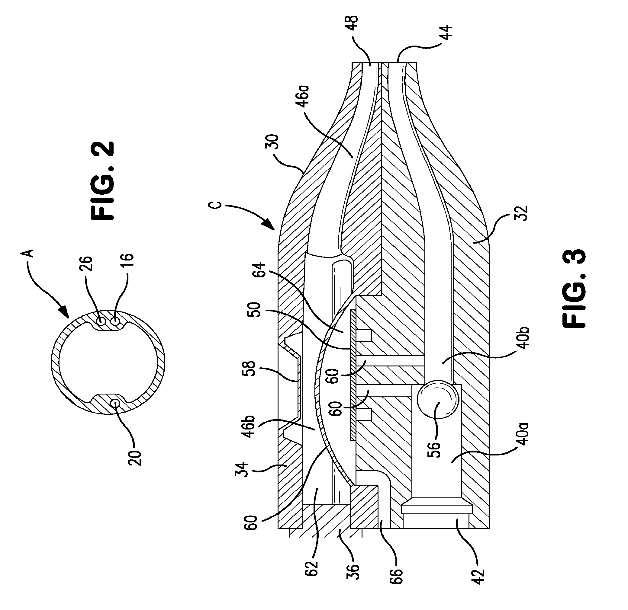
[0020]Fluid under pressure is supplied to the inlet port of the apparatus body. A valve in the pressure cap of the body is secured to the base of the body to create a path to carry fluid from the inlet port of the body to the outlet port of the body, the latter of which is connected to the supply lumen of the balloon. The valve utilizes a pressure responsive deformable member which moves to a position to press on a flexible membrane to seal the fluid flow path to prevent over filling of the retention balloon.

Problems solved by technology

Fecal management systems using an inflated retention balloon must be used carefully because they can create too much pressure on the rectal tissue if the retention balloon is over inflated.
However, this maximum balloon volume can be exceeded by over inflating the balloon, resulting in damage to the soft tissue surrounding the balloon.
Endotracheal systems using an inflated retention balloon must be used carefully because they can create too much pressure on the mucosal tissue in the trachea if the retention balloon is over inflated.
However, this maximum balloon volume or pressure can be exceeded by over inflating the balloon, resulting in damage to the soft tissue surrounding the balloon.
Although one commercially available fecal management system (Flexi-Seal® SIGNAL™ FMS) can be obtained with an indicator that tells the clinician when the balloon is properly filled, there continue to be cases where clinicians have initially over inflated the retention balloon, or have added more fluid to the balloon after the catheter has been in use, resulting in a potentially hazardous situation.
However, that approach has not proved to be practical because in use there are frequently brief periods of muscle contraction in the rectum that result in high pressure in the balloon.
If the inflation fluid were allowed to escape under those high pressure conditions, the retention of the device would be compromised and the catheter expelled or the seal lost.
Accordingly, neither of these approaches has proved successful.
Clearly, devices using this method of calculating the amount of fluid used to inflate the balloon are complex and costly.
Moreover, they have difficulty in taking into account the fact that the fluid can and needs to be able to be withdrawn from the balloon, as well as provided to the balloon, because they cannot easily differentiate between the flow directions.

Method used


Image

  • Apparatus for preventing over inflation of the retention balloon in medical catheters and airway devices
  • Apparatus for preventing over inflation of the retention balloon in medical catheters and airway devices
  • Apparatus for preventing over inflation of the retention balloon in medical catheters and airway devices

Examples


Embodiment Construction

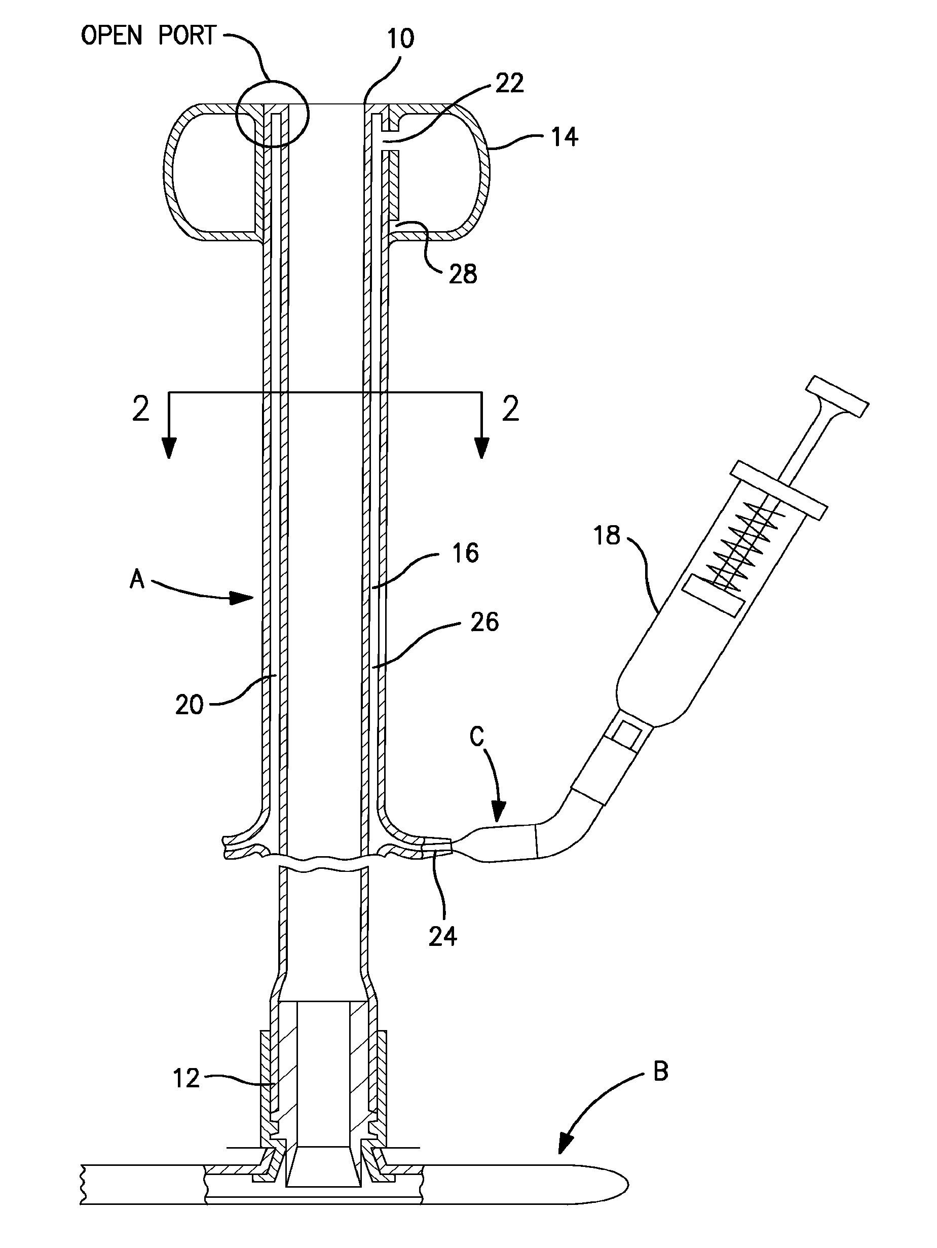
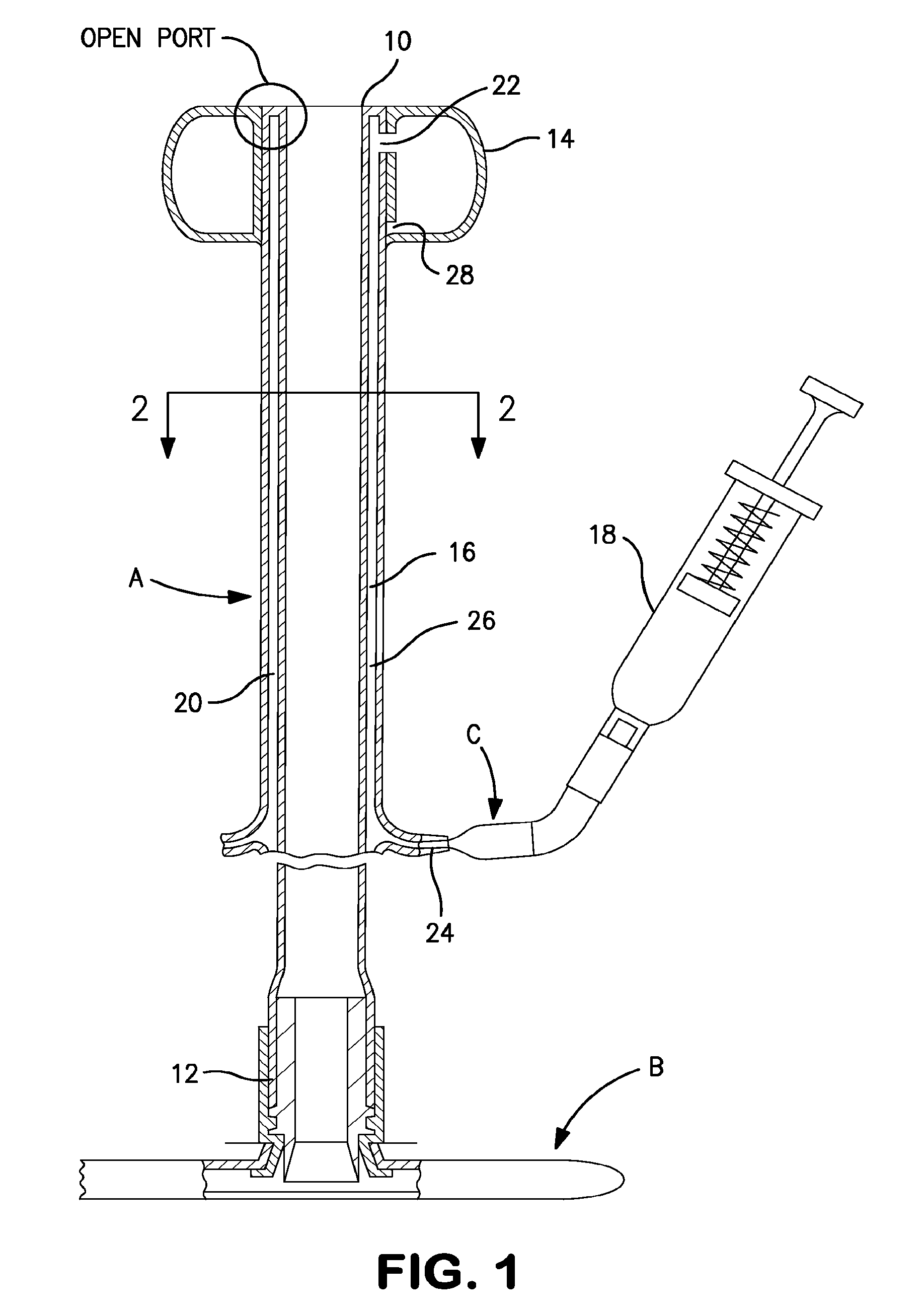
[0092]The present invention is designed for use as part of a tubular medical device which utilizes an inflatable retention balloon. The basic components of one such system are illustrated in FIG. 1. The system is a medical appliance formed of an elongated flexible tubular element or catheter, generally designated A, having a distal end 10 which is introduced into a body cavity, such as the rectum through the anal sphincter or the trachea through the mouth. The proximal end 12 of catheter A is connected to a receptacle, generally designated B, for the collection of fecal waste or an respiratory management system for an endotracheal tube. Affixed to the exterior surface of the distal end 10 of catheter A is a low-pressure inflatable retention balloon 14, shown in its inflated state.

[0093]Balloon 14 is inflated to a suitable diameter with fluid, such as air, water or saline, through a fluid supply lumen 16 after the balloon is inserted into the body cavity such that the distal end of t...


PUM


Abstract

The body has a fluid inlet port for receiving pressurized fluid and a fluid outlet port connected to the retention balloon. A first passage connects the fluid inlet port and the fluid outlet port. A second passage in the body is connected to the balloon fluid return path and is at the pressure of the retention balloon. A valve prevents fluid flow through the first passage when actuated. The valve includes a pressure-responsive member movable to a position to obstruct fluid flow in response to fluid pressure in the second passage exceeding the predetermined level. Flexible means such as a membrane defines a normally open portion of the first fluid passage, which is closed by the moveable means bearing on the membrane when pressure exceeding the predetermined level actuates the valve.

Description

CROSS-REFERENCE TO RELATED APPLICATIONS[0001]This application is filed pursuant to 35 U.S.C. §371 as a United States National Phase Application of International Application Ser. No. PCT / US12 / 65239, filed Nov. 15, 2012, which claims the benefit of U.S. Provisional Patent Application Ser. No. 61 / 650,489, filed Nov. 16, 2011, both of which are incorporated by reference herein in their entirety.BACKGROUND OF THE INVENTION[0002]1. Field of the Invention[0003]The present invention relates to medical devices with inflatable retention balloons and more particularly to an apparatus for preventing over inflation of the catheter retention balloons in a fecal management system or an endotracheal rube.[0004]2. Description of Prior Art Including Information[0005]Fecal management systems, such as the one disclosed in U.S. Pat. No. 8,016,816, issued Sep. 13, 2011 to Christopher C. Gregory, which patent is incorporated herein by reference, are known in the art. The system disclosed in the Gregory pa...

Claims


Application Information

Patent Timeline
Patent Type & Authority Patents(United States)
IPC IPC(8): A61M29/00A61M25/10A61M16/04
CPCA61M25/10183A61M25/10185A61M25/10187A61M25/10182A61M25/10186A61M16/0465A61M16/044A61F5/449A61F2005/4455A61M16/209A61F5/445A61M3/0295A61M16/04A61M16/208A61M2205/583A61M16/0443A61M16/0486A61M16/201
Inventor GREGORY, CHRISTOPHERJIN, YUNCLINE, JOHN B.
Owner CONVATEC TECH INC
Why Eureka
Eureka Blog
Learn More