Hydraulic anchoring assembly for insertable progressing cavity pump

a technology of progressing cavity pump and hydraulic anchoring assembly, which is applied in the direction of fluid removal, borehole/well accessories, construction, etc., can solve the problems of psn not being retrofitted to existing wells, affecting the sealing ability of psn, and large cost for well operators

Active Publication Date: 2018-10-25
INFLATABLE PACKERS INT
View PDF8 Cites 4 Cited by
  • Summary
  • Abstract
  • Description
  • Claims
  • Application Information

AI Technical Summary

Benefits of technology

[0050]Typically, the anchoring assembly also comprises a restriction means, conveniently in the form of one or more cup seals, to provide a pressure differential for inflation of the inflatable packer. The cup seals assist the sucker rod string to deploy the I-PCP down the well at a pump down pressure which is below the pressure at which the packer(s) inflates. The cup seals thereby permit the anchoring assembly to be forced down the well in situations where sucker rods would normally buckle.
[0051]Typically, the anchoring assembly also comprises a premature inflation sleeve to prevent inflation of the inflatable packer during run in via pressurising the annulus upstream of the cup seal.
[0056]Typically, the anchoring assembly also comprises a shearable means in operative association with the hydraulic slip means such that further pull up on the rods releases the hydraulic slip means and allows the anchoring assembly to be removed from the well.
[0059]Optionally, the anchoring assembly may have multiple inflatable packers. The use of two inflatable packers becomes important where well conditions do not permit full inflation of a single inflatable packer. For example, were a cup seal is used proximate the upstream end of the anchoring assembly, there may be insufficient pressure differential to achieve full inflation of the inflatable packer, due to damage of the cup seal during run-in of the anchoring assembly. To avoid such situations a second inflatable packer, located downstream of the first mentioned inflatable packer, is provided and can achieve full inflation because of the pressure differential created by the partially inflated packer located upstream of it.

Problems solved by technology

The expense and logistics required for this operation have led to the development of an alternative method of installation as a contingency to be used when the main PCP fails.
An I-PCP offers cost advantages compared to traditional repair / replacement of the original PCP stator, and mitigate the need to remove the original production tubing, which otherwise results in large costs to the well operators.
However, one challenge of installing an I-PCP is anchoring the stator to the well casing with the PSN, which is prone to corrosion and internal profile / surface damage which compromises its ability to seal.
Another disadvantage is that a PSN cannot be retrofitted to existing wells.
It is also for this reason that the PSN is prone to damage as it is exposed to the well bore environment for long durations before it is actually required for use—when the main PCP is damaged and an I-PCP is installed in its place.
Which means when the PSN is required for the deployment of an I-PCP, it may no longer be in a condition suitable for use There is a further issue that the location of the landing zone for the PSN may be in the wrong place as information gathered over the life of the well suggest that a different pump location is required for the further operation of the well.
Another challenge faced when landing the I-PCP into a PSN, is that it normally requires a certain amount of force to land the I-PCP into the PSN.
There are situations where the PSN has been installed at great depths and / or in a horizontal section of the well, whereby the sucker rods lack the compressive strength to transmit the necessary force required to land the I-PCP into the PSN.
Each of these issues requires removal of the production tubing to reposition and / or replace the PSN, which counter acts the benefits offered by installing an I-PCP.
The problem of the mechanical I-PCP anchor is that it requires axial forces to set, which means it requires a drag assembly to provide the necessary resistance to initiate the setting procedure.
This method increases the risk of premature deployment.
This method of setting also makes it difficult or sometimes impossible to set the anchor in highly deviated or deep wells, whereby the load required to set cannot be transmitted through the sucker rods it is deployed on.
Further, the mechanical I-PCP anchor seal is prone to leakage given its limited seal expansion and limited effective length of contact with the production tubing.
Also, the mechanical I-PCP anchor has a limited ability to comply to the tubing profile, as stresses acting on the tubing can cause it to go out of round, inability to comply to tubing ID tolerances, or inability to seal on surfaces which are pitted, scored or corroded.
An issue with the mechanical I-PCP anchor is that it requires manipulation of the drill rods in order to change modes of operation.
The disadvantage of using a J-latch is that in deep and deviated wells it can be difficult for the operator to determine how much downward or upward force to apply to the drill rods to move the J-latch to the next operational position.
This lack of “feel” can result in the operator dragging or pushing the mechanical anchor inside the casing and thereby damaging the casing and producing wear in the mechanical anchor and reducing the life of the anchor or resulting in a poorly set anchor and seal, which compromises function of the I-PCP and reduces the rate well fluid can be pumped from the well.
A further limitation of Mechanical I-PCP anchor is that they cannot seal into an unlined open hole well.
Instead an I-PCP must be sealed to casing or tubular due to their limited expansion and compliance.
However, mechanical packers rely upon longitudinal compression to achieve radial expansion, whereas inflatable packers rely upon inflation via high pressure well fluids to increase the radial dimension of the elastomeric sleeve which results in shortening of the length of the sleeve.
In highly deviated wells there is considerable friction between the well bore and the drill string, which results in unpredictability in the number of turns of the drill string needed to expand a mechanical packer.
Also, in such wells rotation of the drill string can lead to part of the drill string above the PCP or I-PCP unthreading and dropping the PCP / I-PCP down the well and necessitating costly retrieval processes (referred to as “fishing”).

Method used


Image

  • Hydraulic anchoring assembly for insertable progressing cavity pump
  • Hydraulic anchoring assembly for insertable progressing cavity pump
  • Hydraulic anchoring assembly for insertable progressing cavity pump

Examples


first embodiment

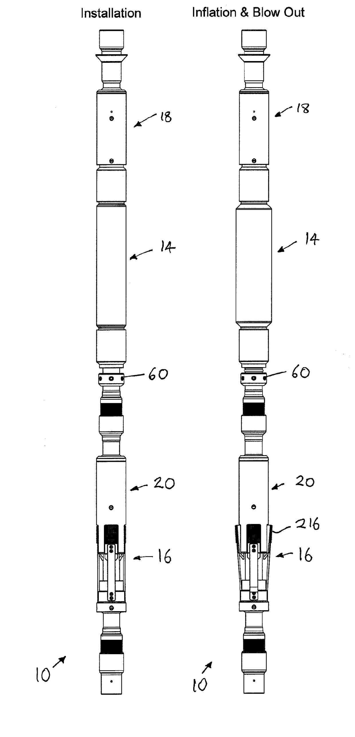
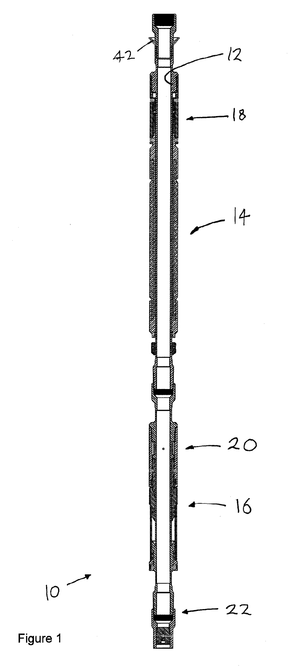
[0092]As shown in FIG. 1 the hydraulic anchoring assembly 10 of the present invention comprises an inner mandrel 12, an inflatable packer 14 and a hydraulic slip 16 both set upon the inner mandrel, a one-way valve 18 in fluidic communication with the inflatable packer 14, a one-way deployment valve 20 in fluidic communication with the hydraulic slip 16, a sealing means 22, and a release means 24 for deflating the inflatable packer 14 and releasing the hydraulic slip 16. The hydraulic anchoring assembly 10 is intended for deployment with an I-PCP in a well (not shown) for pumping well fluids out of the well to the surface of the well.

[0093]The I-PCP has a rotor and a stator (not shown). The rotor is attached to and driven by sucker rods (not shown) and the stator is attached to the inner mandrel 12 at the upstream end of the hydraulic anchoring assembly 10. Prior to deployment the stator the I-PCP is attached to the inner mandrel 12 of the hydraulic anchoring assembly 10 and the pair...

second embodiment

[0147]The main differences between the second embodiment 10a and the first embodiment 10 is that there are two or more cups seals 42 and two or more inflatable packers 14 and 14a. The reason for the second cup seal 42 is to improve the pressure differential experienced by the upstream inflatable packer 14 to improve its chances of inflating. The reason for the second inflatable packer 14a (located downstream of the first inflatable packer 14) is to guarantee a seal between an I-PCP (not shown) and production tubing is achieved even where the upstream inflatable packer 14 does not achieve full inflation.

[0148]As shown in FIGS. 7a to 7c the hydraulic anchoring assembly 10a of the present embodiment comprises an inner mandrel 12, an upstream inflatable packer 14, a downstream inflatable packer 14a and a hydraulic slip 16 both set upon the inner mandrel 12. The anchoring assembly 10a also comprises a one-way valve 18 in fluidic communication with the inflatable packer 14, another one-wa...


PUM


Abstract

A hydraulic anchoring assembly (10, 10a), and method of its use, for anchoring and sealing an insertable progressing cavity pump on rods in a well. The assembly (10, 10a) has one or more cup seals (42, 42a), upstream of one or more inflatable packers (14, 14a) upstream of one or more hydraulic slips (16). The cup seals (42, 42a) provide a pressure differential for inflation of the upstream most inflatable packer (14), which in turn provides a pressure differential for the downstream inflatable packer(s) (14a) to inflate to produce a fluid tight seal between the insertable progressing cavity pump and the well. In highly deviated wells the up seals (42, 42a) can be used to pump the hydraulic anchoring assembly (10, 10a) down the well in situations where the rods would otherwise buckle.

Description

FIELD OF THE INVENTION[0001]The present invention relates to a hydraulic anchoring assembly for insertable progressing cavity pump (I PCP).[0002]More particularly, the present invention relates to a hydraulic anchoring assembly for anchoring and sealing an I-PCP without the use of a pump seating nipple (PSN).[0003]Further, the present invention relates to a hydraulic anchoring assembly for I-PCP's which provides sealing with one or more inflatable packers, instead of a mechanical packer, and which assembly provides anchoring with hydraulic slip, instead of a mechanical slip.[0004]Further, the present invention relates to a hydraulic anchoring assembly that uses a fluid restriction (typically in the form of one or more cup seals) located upstream of the or all of the inflatable packers, to provide a pressure differential sufficient to cause inflation of the or each inflatable packers.[0005]Further, the present invention relates to a hydraulic anchoring assembly for deploying I-PCP's ...

Claims


Application Information

Patent Timeline
Patent Type & Authority Applications(United States)
IPC IPC(8): E21B23/01E21B33/127E21B33/129E21B43/12E21B34/06E21B34/10
CPCE21B23/01E21B33/127E21B33/1293E21B43/121E21B34/063E21B34/10E21B2034/007E21B43/126E21B2200/06
Inventor FORD, FRANCIS JOHN GUILLENA
Owner INFLATABLE PACKERS INT
Why Eureka
Try Eureka