Stabilizing Adjustable Shooting Device

Inactive Publication Date: 2013-11-14
MAHNKE III DANIEL A
View PDF15 Cites 4 Cited by
  • Summary
  • Abstract
  • Description
  • Claims
  • Application Information

AI Technical Summary

Benefits of technology

[0012]The invention provides the security of the sand bag devices by using a media bag filled with a weighted granular media sectioned strategically with stitching to provide lateral stability of the invention as well as the security of the firearm. Using the strategic stitching layout and the weighted media bag, the invention resists the roll effect of the conventional devices and provides the security and stability offered by the burdensome sand bag and mechanical vice type devices. The sectional media body folds in two forming a dual layer system. Folded between the sectional media body is an air bladder. The air bladder is inflated or deflated by an air supply (

Problems solved by technology

The current state of the art lacks a device which allows the shooter to precisely adjust the alignment of the firearm efficiently without abandoning the firing position, while still providing the stability that the bulky sand bag type devices provide, all while maintaining a stable, lightweight, portable, and efficient design.
Such “sand bag” devices are used to rest the gun stock on for long range shooting but do not assist in sighting in on a target.
Rather, common shooting bags are used to simply rest the rifle during the shooting process and offer limited adjustability.
The simplicity and stability the “sand bag” type firearms provide often restrict the shooter's ability to precisely adjust the alignment of the firearm.
Because the sand bag is nearly impossible to precisely tune the dimensions of, shooters are often left contorting their positions to acquire the proper firearm alignment.
While these mechanical structures offer a greater precision in adjustability than those of the “sand bag” type shooting rests, they are cumbersome, heavy, and require the shooter to abandon the shooting position to adjust the horizontal and vertical alignment of the firearm.
The rigidity, size, and bulkiness that afford the shooter the increased adjustability and security of these mechanical structures often imped

Method used


Image

  • Stabilizing Adjustable Shooting Device
  • Stabilizing Adjustable Shooting Device
  • Stabilizing Adjustable Shooting Device

Examples


Example

[0025]The following list provides a brief description of each item number. Item number designations remain consistent among the several figures:

[0026]Item 1 designates the polypropylene air bladder.

[0027]Item 2 designates the friction sock.

[0028]Item 3 designates the complete sectional media body.

[0029]Item 4 designates the media contained in Item 3.

[0030]Item 5 designates the air supply hose.

[0031]Item 6 designates the air supply valve.

[0032]Item 7 designates the air supply pump.

[0033]Item 8 designates the outer cover.

[0034]Item 9 designates the sectional stitching.

[0035]Item 10 designates the firearm.

[0036]Item 11 designates the bipod (not required for use of this invention).

[0037]Item 12 designates the completed shooting bag.

[0038]Item 13 designates the shooting surface upon which the shooting bag rests.

[0039]Item 14 designates the individual media sections formed by the sectional stitching.

DETAILED OVERVIEW OF THE INVENTION

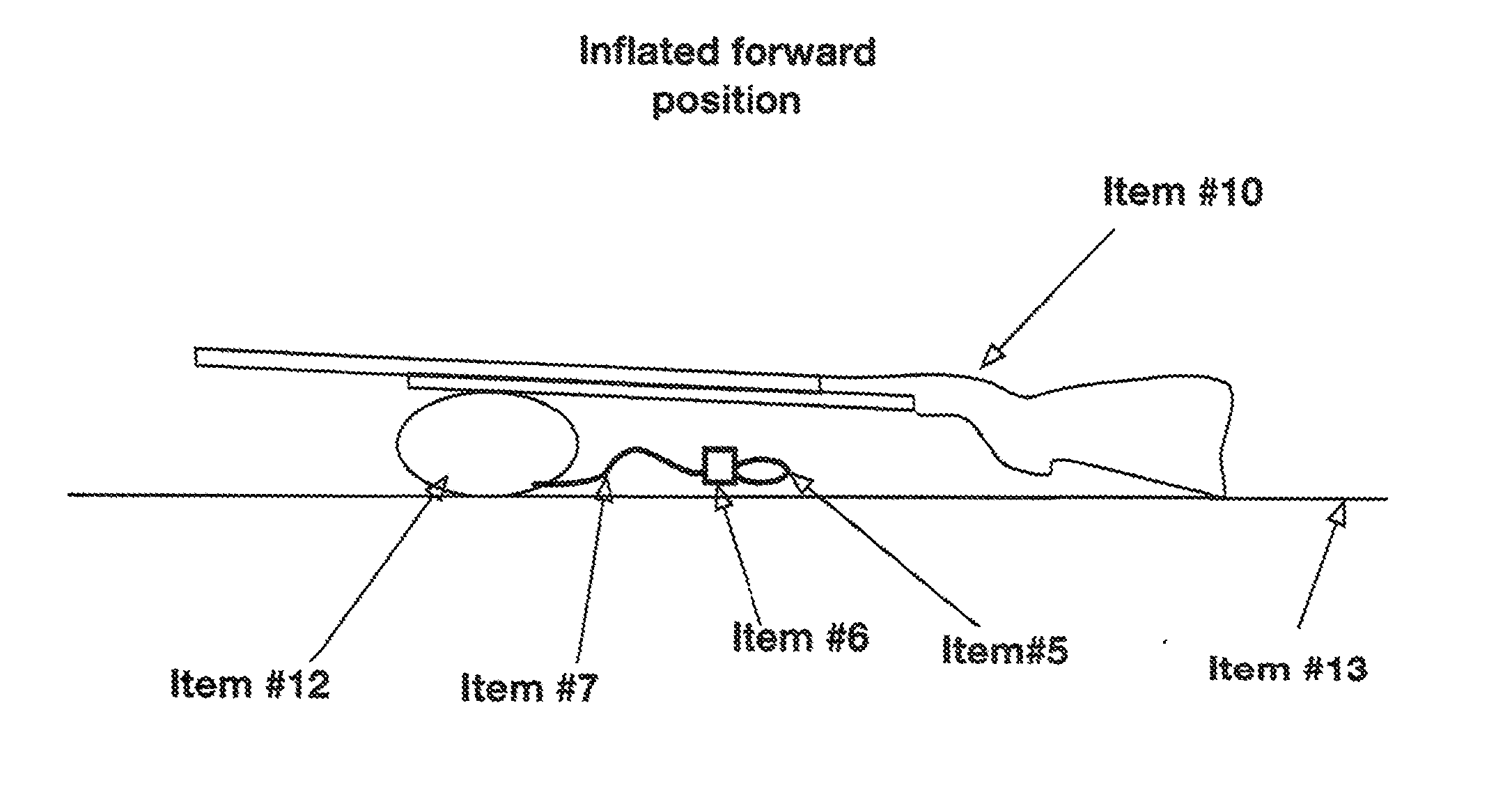
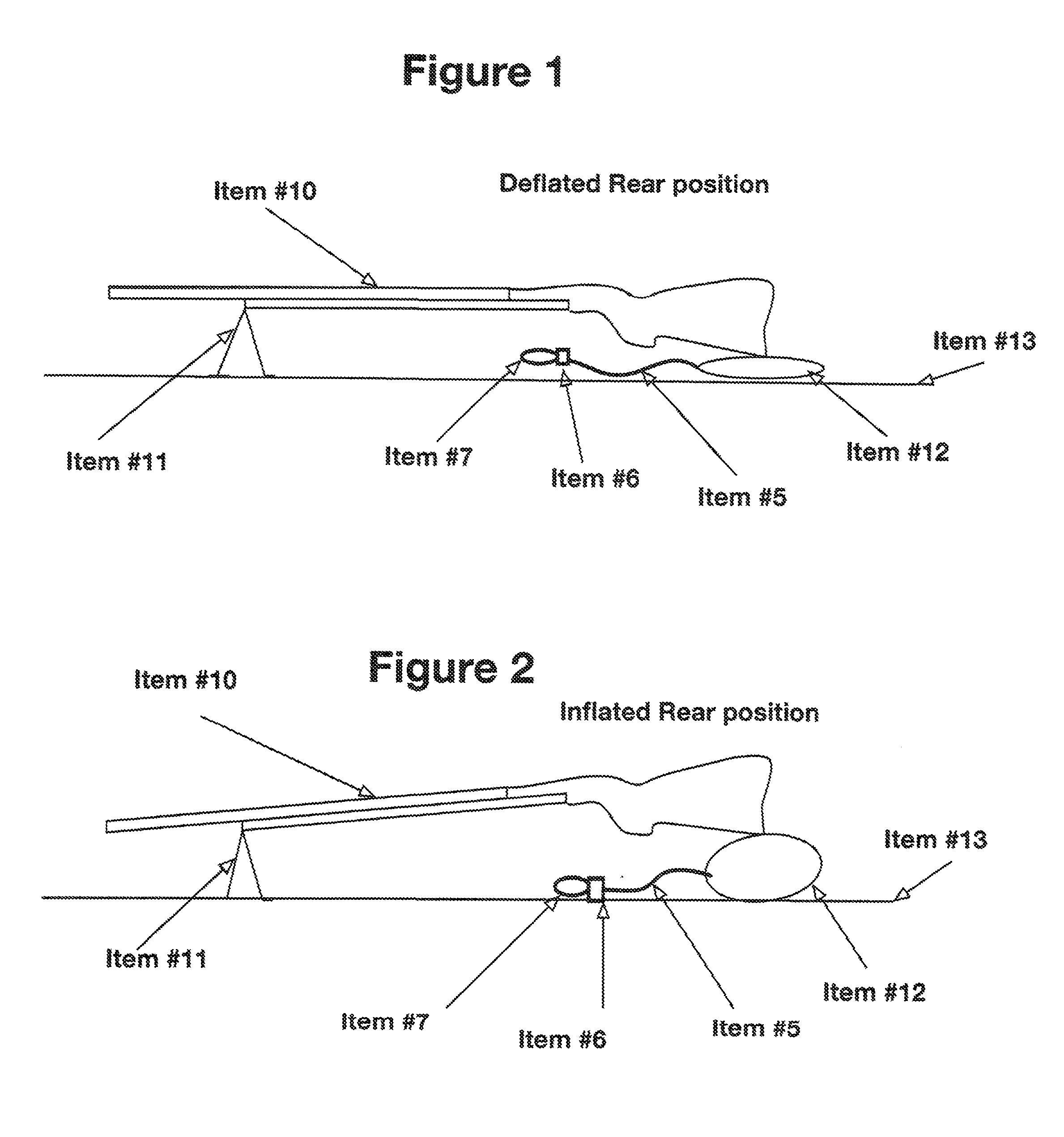
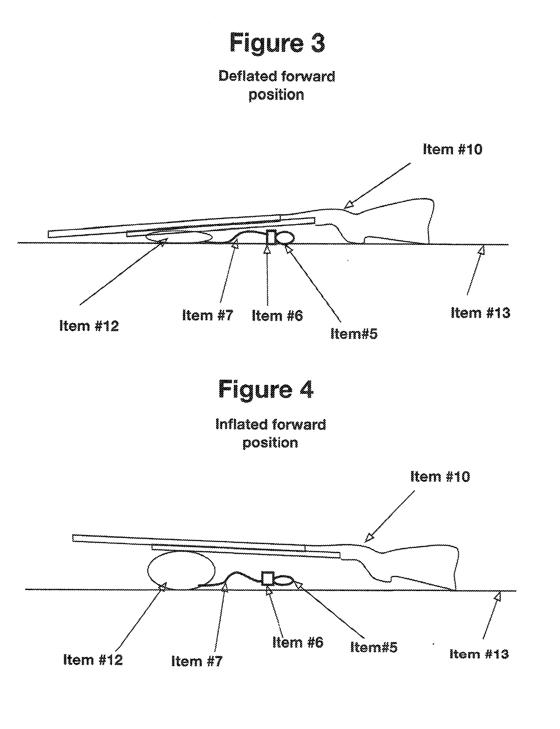
[0040]This invention utilizes a seamless polypropylene a...


PUM


Abstract

An air adjustable shooting bag that utilizes a sectional media body, air bladder and friction sock, and outer containment bag to adjust alignment of the firearm wherein the shooter positions the barrel or the stock of the firearm upon the flexible media body to stabilize the firearm during firing and the air bladder is used to expand or contract the media body. The invention provides the stability of popular “sand bag” type shooting rests and the fine-tune adjustability of rigid “mechanical vice” type shooting systems while maintaining the lightweight and portable characteristics of “balloon type” shooting bags.

Description

CROSS-REFERENCE TO RELATED APPLICATIONS[0001]See Application Data SheetSTATEMENT REGARDING FEDERALLY SPONSORED RESEARCH OR DEVELOPMENT[0002]Not ApplicableTHE NAMES OF THE PARTIES TO A JOINT RESEARCH AGREEMENT[0003]Not ApplicableINCORPORATION-BY-REFERENCE OF MATERIAL SUBMITTED ON A COMPACT DISC[0004]Not ApplicableREFERENCE TO “MICROFICHE APPENDIX”[0005]Not ApplicableSTATEMENT REGARDING SUBSTITUTE SPECIFICATION[0006]This Substitute Specification contains no new matter.BACKGROUND OF THE INVENTION[0007]In the sport of long range precision shooting, conventional methods of firearm rests or supports typically provide the shooter with a combination of only two of the following benefits: a high degree of precision, stability of the firearm, flexibility to allow the shooter to fire from a variety of positions in various environments, portability, and efficiency in firing multiple shots precisely. The current state of the art lacks a device which allows the shooter to precisely adjust the ali...

Claims


Application Information

Patent Timeline
IPC IPC(8): F41A23/02
CPCF41A23/16F41A23/02
Inventor MAHNKE, III, DANIEL A.
Owner MAHNKE III DANIEL A
Why Eureka
Try Eureka