Segmented balloon catheter

a catheter and balloon technology, applied in the field of catheter improvement, can solve the problems of asynchronous rhythm and disruption of normal cardiac cycle, and achieve the effect of stably pressing

Active Publication Date: 2015-05-07
BIOSENSE WEBSTER (ISRAEL) LTD
View PDF6 Cites 4 Cited by
  • Summary
  • Abstract
  • Description
  • Claims
  • Application Information

AI Technical Summary

Benefits of technology

[0012]There is further provided according to embodiments of the invention a method of catheterization, which is carried out by introducing a catheter into a heart chamber of a subject. The distal portion of the catheter includes an inflatable assembly. The inflatable assembly includes a containment chamber, an axial core and a plurality of longitudinally oriented partitions extending from the axial core to the wall of the chamber to divide the containment chamber into at least four inflatable sectors. The sectors are externally delimited by respective bounding portions of the outer surface. Hydraulic valves are connected to respective sectors to enable selective inflation of the sectors by a fluid when the valves are connected to a source of the fluid, and at least one surface electrode is mounted on each of the bounding portions. The method is further carried out by inflating a selected one of the pairs of the sectors sufficiently to stably press the outer surface of the pairs of the inflated sectors against the walls of the heart chamber while avoiding inflation of others of the sectors, wherein the at least one surface electrode of each sector of the selected pair contacts the walls of the heart chamber.

Problems solved by technology

Cardiac arrhythmias, such as atrial fibrillation, occur when regions of cardiac tissue abnormally conduct electric signals to adjacent tissue, thereby disrupting the normal cardiac cycle and causing asynchronous rhythm.

Method used


Image

  • Segmented balloon catheter
  • Segmented balloon catheter
  • Segmented balloon catheter

Examples


Embodiment Construction

[0022]In the following description, numerous specific details are set forth in order to provide a thorough understanding of the various principles of the present invention. It will be apparent to one skilled in the art, however, that not all these details are necessarily always needed for practicing the present invention. In this instance, well-known circuits, control logic, and the details of computer program instructions for conventional algorithms and processes have not been shown in detail in order not to obscure the general concepts unnecessarily.

System Description

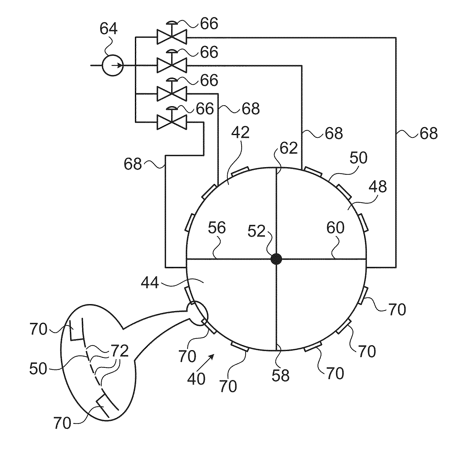
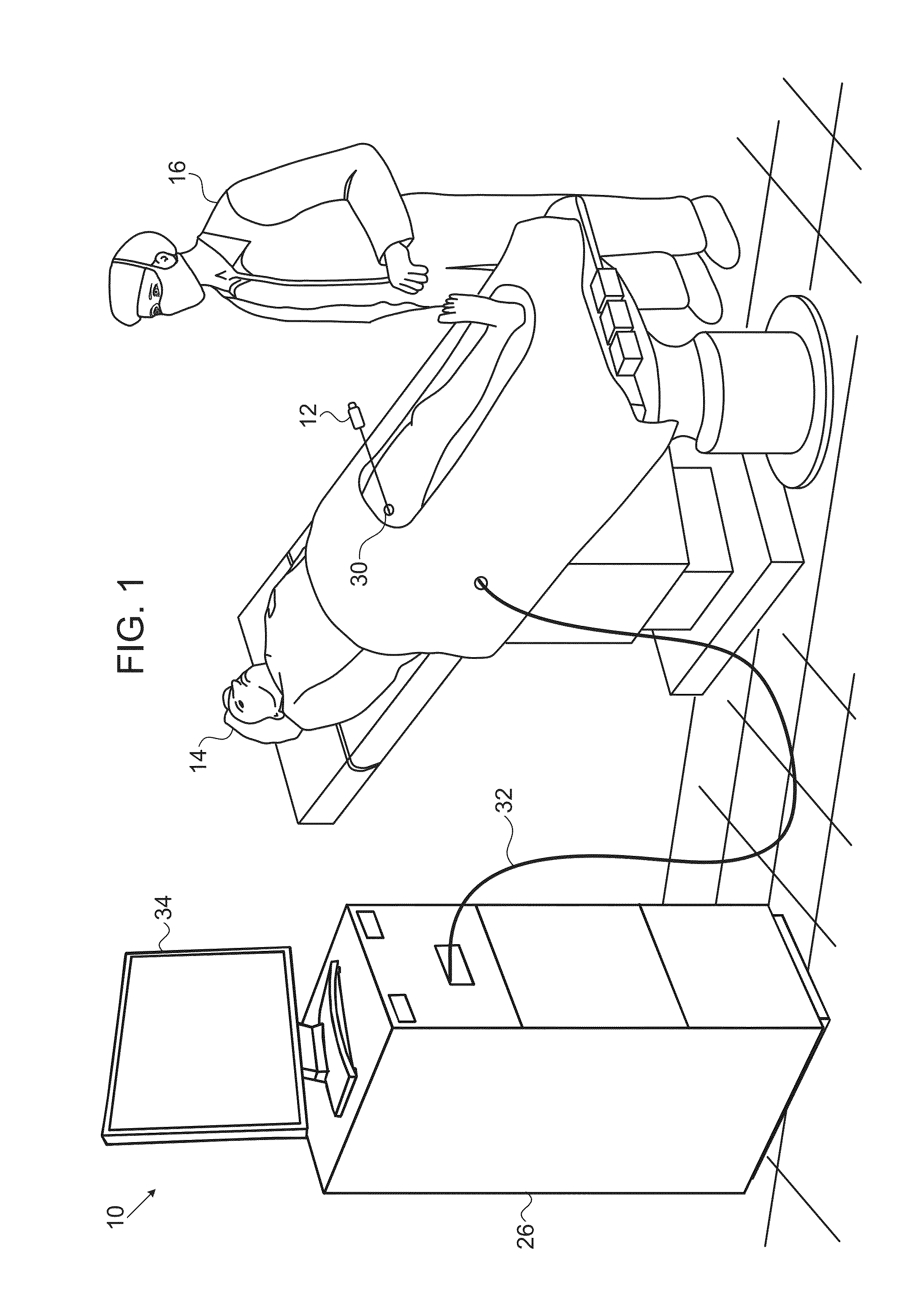
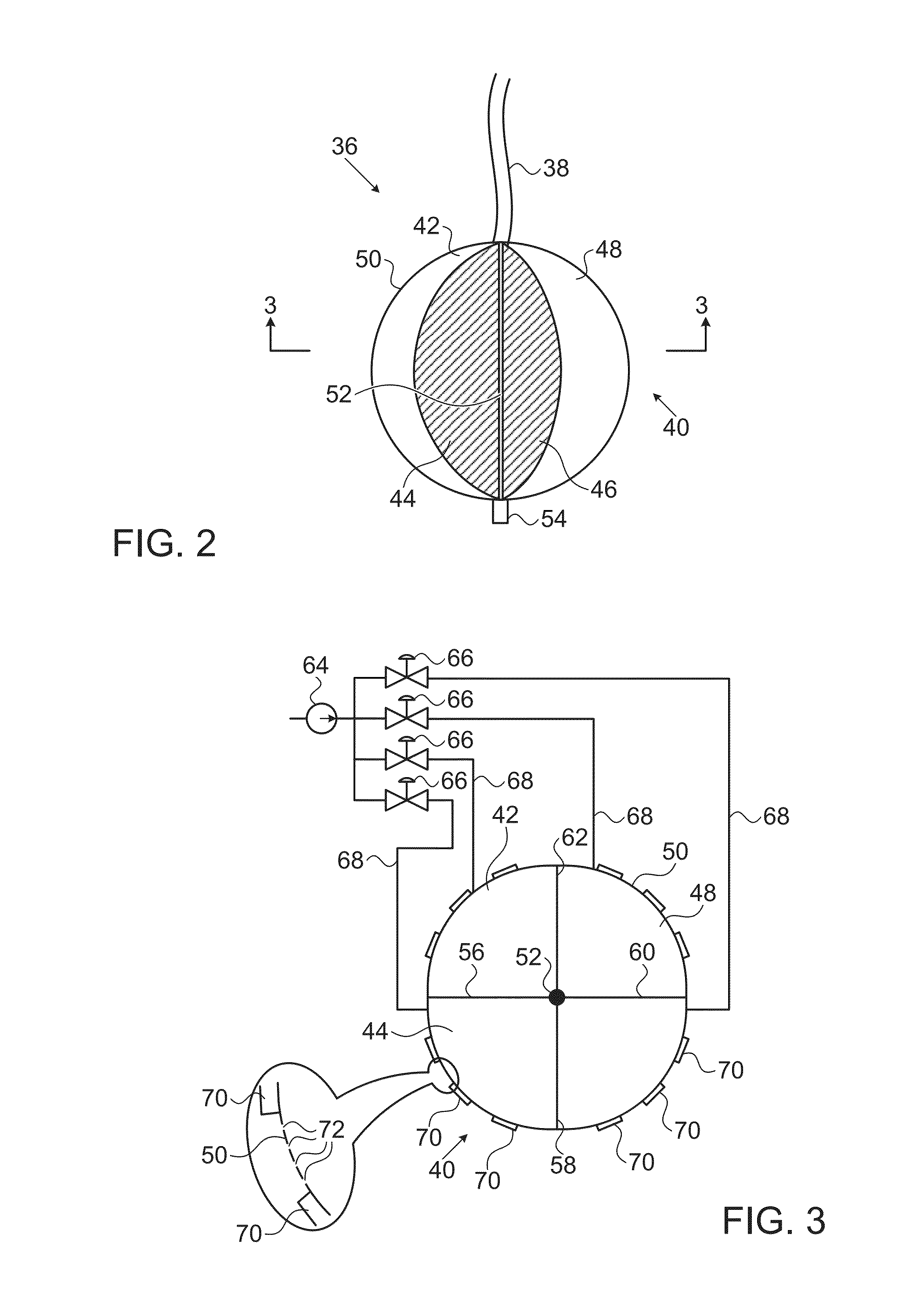
[0023]Turning now to the drawings, Reference is initially made to FIG. 1, which is a schematic, pictorial illustration of a vascular catheterization system 10 in accordance with an embodiment of the present invention. Use of the system 10 involves inserting a catheter 12 into the body of a subject 14 at an insertion point 30, for example a femoral artery or vein; thence into an internal body cavity, such as a heart ch...


PUM


Abstract

A catheter has an inflatable assembly at its distal portion, including a containment chamber, an axial core and a plurality of longitudinally oriented partitions extending from the axial core to the wall of the chamber to divide the containment chamber into at least four inflatable sectors. Hydraulic valves are connected to respective sectors to enable selective inflation of the sectors by a fluid when the valves are connected to a source of the fluid, and at least one surface electrode is mounted on each of the sectors. When introduced into a heart chamber and diametrically opposed sectors are inflated the assembly is stably fixed against the walls of the heart chamber and readings can be obtained from the surface electrodes of the inflated sectors.

Description

BACKGROUND OF THE INVENTION[0001]1. Field of the Invention[0002]This invention relates generally to methods and devices for invasive medical treatment. More particularly, this invention relates to improvements in catheters.[0003]2. Description of the Related Art[0004]Cardiac arrhythmias, such as atrial fibrillation, occur when regions of cardiac tissue abnormally conduct electric signals to adjacent tissue, thereby disrupting the normal cardiac cycle and causing asynchronous rhythm.[0005]Procedures for treating arrhythmia include surgically disrupting the origin of the signals causing the arrhythmia, as well as disrupting the conducting pathway for such signals. By selectively ablating cardiac tissue by application of energy via a catheter, it is sometimes possible to cease or modify the propagation of unwanted electrical signals from one portion of the heart to another. The ablation process destroys the unwanted electrical pathways by formation of non-conducting lesions.[0006]One s...

Claims


Application Information

Patent Timeline
Patent Type & Authority Applications(United States)
IPC IPC(8): A61M25/10A61B5/0408A61B18/14
CPCA61M25/10185A61B5/0408A61B18/1492A61B2018/0022A61B18/1206A61B2018/0016A61B2018/00267A61B2018/00357A61B2018/00577A61B5/25A61B5/287A61B2018/00029A61B2018/00065A61B2018/00261A61B2018/00351
Inventor LEVIN, MICHAELLICHTENSTEIN, YOAVREUVENI, AVIROSENBERG, AVIGDOR
Owner BIOSENSE WEBSTER (ISRAEL) LTD
Why Eureka
Try Eureka