Intraluminal stent graft

a technology of stents and grafts, applied in the field of intraluminal stent grafts, can solve the problems of limited thinness of the wall, limited ability of the tube to be contracted into a small cross-sectional area, and occasional mortality

Inactive Publication Date: 2006-04-06
GORE ENTERPRISE HLDG INC
View PDF43 Cites 16 Cited by
  • Summary
  • Abstract
  • Description
  • Claims
  • Application Information

AI Technical Summary

Problems solved by technology

These types of repairs consequently cause major trauma to the patient with corresponding lengthy recovery periods and may result in occasional mortality.
The difficulty with the use of either the GORE-TEX Vascular Graft or the Impra graft as the sleeve component is that the relatively thick, bulky wall of the extruded, longitudinally expanded PTFE tubes limits the ability of the tube to be contracted into a small cross-sectional area for insertion into a blood vessel.
The thinness of the wall is limited by the difficulty of manufacturing an extruded, longitudinally expanded tube having a thin wall of uniform thickness.

Method used


Image

  • Intraluminal stent graft
  • Intraluminal stent graft
  • Intraluminal stent graft

Examples


example 1

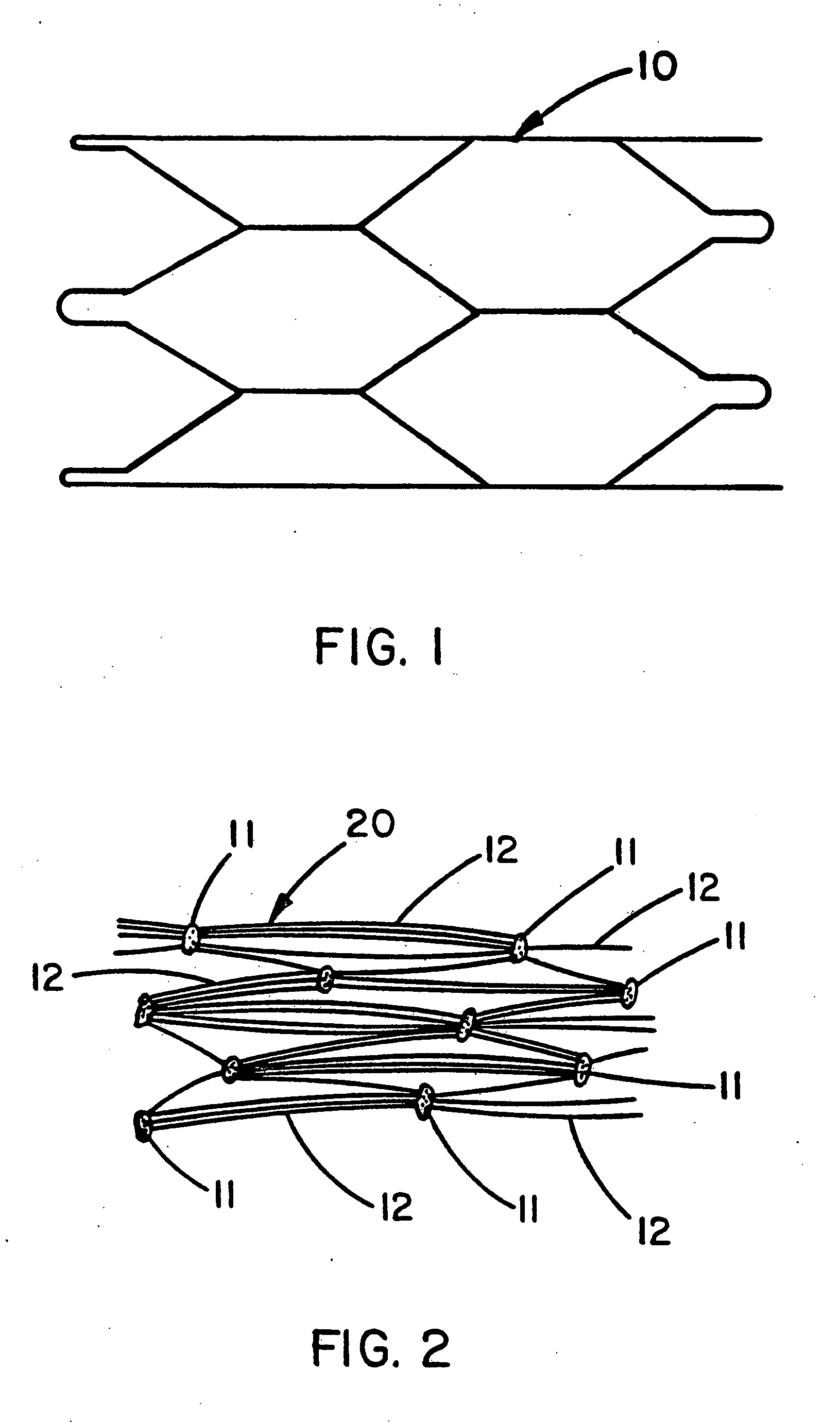
[0030] A Nitinol wire stent 10 (Nitinol Medical Technologies, Boston, Mass.) of the type described by FIG. 1 was provided with both a luminal covering and an exterior covering of expanded PTFE film. This 3 cm long stent was formed from 0.25 mm diameter Nitinol wire into a tubular shape of interlocking hexagons. The luminal and exterior coverings were both made from a uniaxially-oriented film having fibrils oriented substantially in a single direction wherein the fibrils were all substantially parallel to each other. The luminal covering was provided with the fibrils oriented parallel to the longitudinal axis of the tubular stent; the exterior covering was provided with the fibrils oriented substantially circumferential to the tubular stent. The film used for both the luminal and exterior coverings was a porous expanded PTFE film having a discontinuous, porous coating of FEP applied to one side of the porous expanded PTFE film. Examination of the FEP coated side of the film by scanni...

example 2

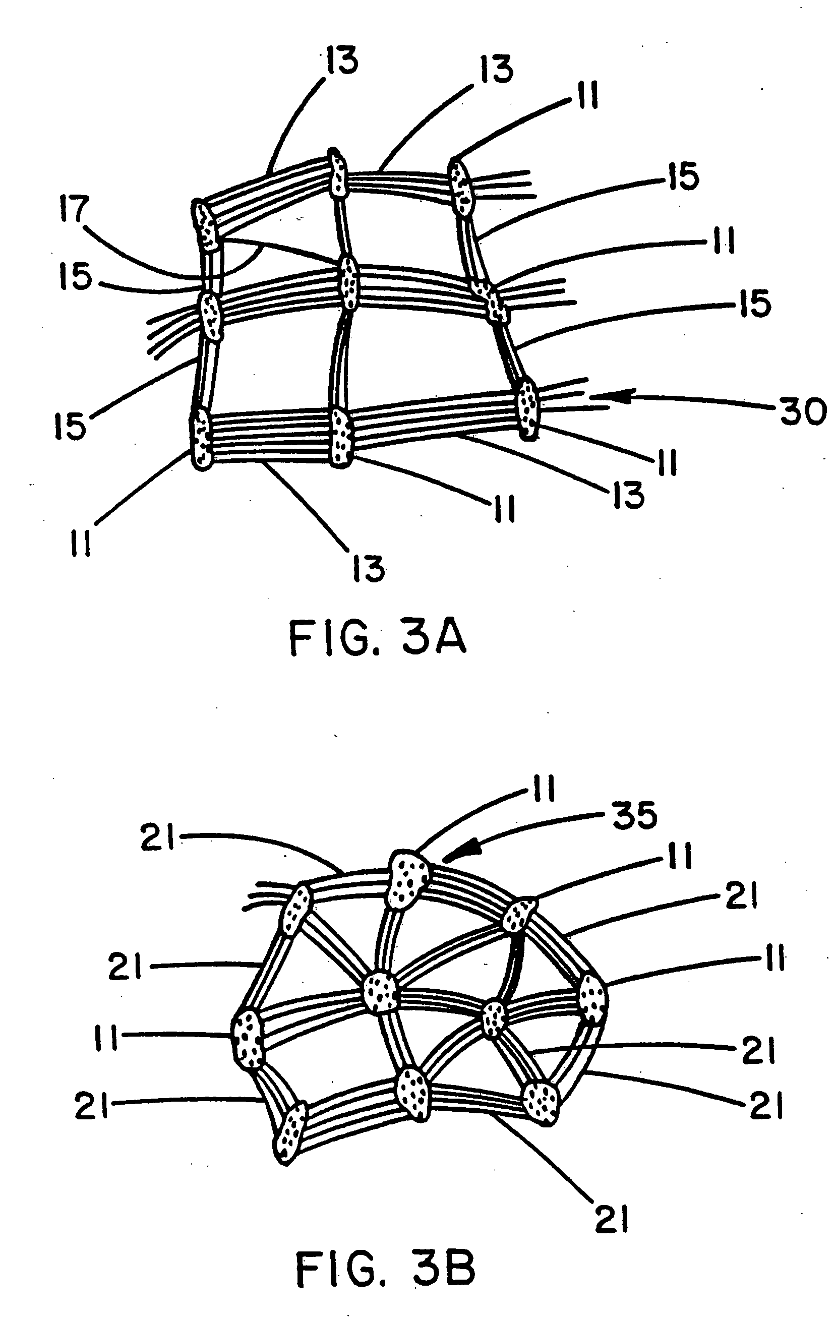
[0041] A Nitinol wire stent of the same type used for Example 1 was provided with a luminal covering of a porous expanded PTFE film having a microstructure of biaxially-oriented fibrils as shown by FIG. 3A. This was accomplished by wrapping a hollow tubular mandrel of non-porous PTFE with a layer of porous expanded PTFE film having a continuous (non-porous) coating of FEP with the FEP-coated side of the film facing outwardly away from the mandrel surface. This film was about 0.02 mm thick; the porous expanded PTFE had a microstructure of uniaxially-oriented fibrils with the fibrils oriented circumferentially about the exterior surface of the mandrel. The Nitinol stent was carefully fitted over the film-wrapped portion of the mandrel. The mandrel assembly was then placed into an oven set at 360° C. for four minutes. After removal from the oven and subsequent cooling, the mandrel was removed from the stent leaving the wrapped film adhered to the luminal surface of the stent. This film...

example 3

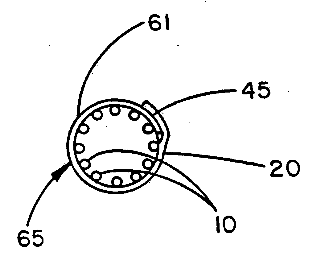
[0045] A Palmaz stent of the balloon-expandable type (part no. PS30, Johnson & Johnson Interventional Systems, Inc., Warren, N.J.) was adjusted from its collapsed outside diameter of 3.4 mm to an enlarged outside diameter of 8.0 mm by inserting a tapered stainless steel mandrel followed by a straight 8.0 mm diameter stainless steel mandrel. This stent was then provided with a single layer exterior wrapping of the same discontinuously FEP-coated porous expanded PTFE coating used for the exterior wrapping of the stent of Example 1. This was accomplished by wrapping the film about the exterior surface of the mandrel with the uniaxially-oriented fibrils of the film microstructure oriented parallel to the longitudinal axis of the stent. This exterior covering 61 is described by the transverse cross section of FIG. 6. A 2 mm wide seam 45 was formed from the overlapped edges of the porous expanded PTFE film 20 by temporarily placing a thin sheet of polyamide film over these edges and apply...


PUM

PropertyMeasurementUnit
diameteraaaaaaaaaa
thicknessaaaaaaaaaa
thickaaaaaaaaaa

Abstract

A method of making an tubular intraluminal graft in the form of a tubular diametrically adjustable stent having a tubular covering of porous expanded polytetrafluoroethylene which is less than 0.10 mm thick. The covering may be on the exterior surface of the stent, or on the interior surface of the stent, or both. The covering may be affixed to the stent by an adhesive which is preferably fluorinated ethylene propylene.

Description

CROSS REFERENCE TO RELATED APPLICATIONS [0001] This application is a continuation of U.S. application Ser. No. 10 / 413,731 which is a continuation of U.S. application Ser. No. 10 / 083,461 (U.S. Pat. No. 6,547,815) which is a continuation of U.S. application Ser. No. 09 / 306,522 (U.S. Pat. No. 6,357,104) which is a division of U.S. application Ser. No. 08 / 872,837 (U.S. Pat. No. 5,925,075), which is a continuation of U.S. application Ser. No. 08 / 109,214 (U.S. Pat. No. 5,735,892).FIELD OF THE INVENTION [0002] This invention relates to the field of intraluminal grafts and particularly to a method of making thin-wall intraluminal grafts useful as an inner lining for blood vessels or other body conduits. BACKGROUND OF THE INVENTION [0003] Conventional vascular grafts have long been used for vascular repair in humans and animals. These devices are typically flexible tubes of woven or knitted polyethylene terephthalate or of porous polytetrafluoroethylene (hereinafter PTFE). Grafts of biologic...

Claims


Application Information

Patent Timeline
Patent Type & Authority Applications(United States)
IPC IPC(8): A61F2/06A61F2/00A61F2/82A61F2/90A61L31/10
CPCA61F2/07Y10T29/49982A61F2/90A61F2002/072A61F2002/075A61F2210/0014A61F2240/001A61L31/10A61F2/82Y10T156/1005Y10T29/4998Y10T156/1033C08L27/18
Inventor LEWIS, JAMES D.MYERS, DAVID J.HOUSE, WAYNE D.
Owner GORE ENTERPRISE HLDG INC
Why Eureka
Try Eureka